And There Was Light (or The Van eBay Built)...
My wife and I are converting a delivery van into a motorhome in the following three phases:
Lining and insulationFurniture and beddingGas, water and electrical
This post deals mostly with the electrical installation, which is part of the last (third) phase of the conversion.
If you just want to look at pictures, here is a running project photo journal with the most recent photos at the top.
Costs
The electrical kit alone cost around £1,800, not including additional tools (e.g. amp meter, hydraulic crimper, etc.), solar panels and appliances. It is the third biggest cost after the van itself and the furniture.
AC/DC
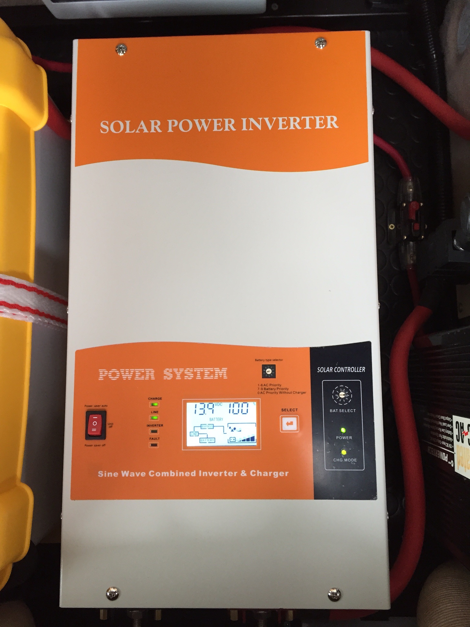
I decided to have both 12VDC and 230VAC supply in the van, because we have loads requiring one or the other. At the heart of the electrical system is a 2000 Watt, 12VDC inverter/charger/solar MPPT controller (or UPS) from SANTAK - EATON. This unit is an OEM version of the popular units on the market, albeit at half the price of the western counterparts and is shipped directly from the factory in China via DHL.
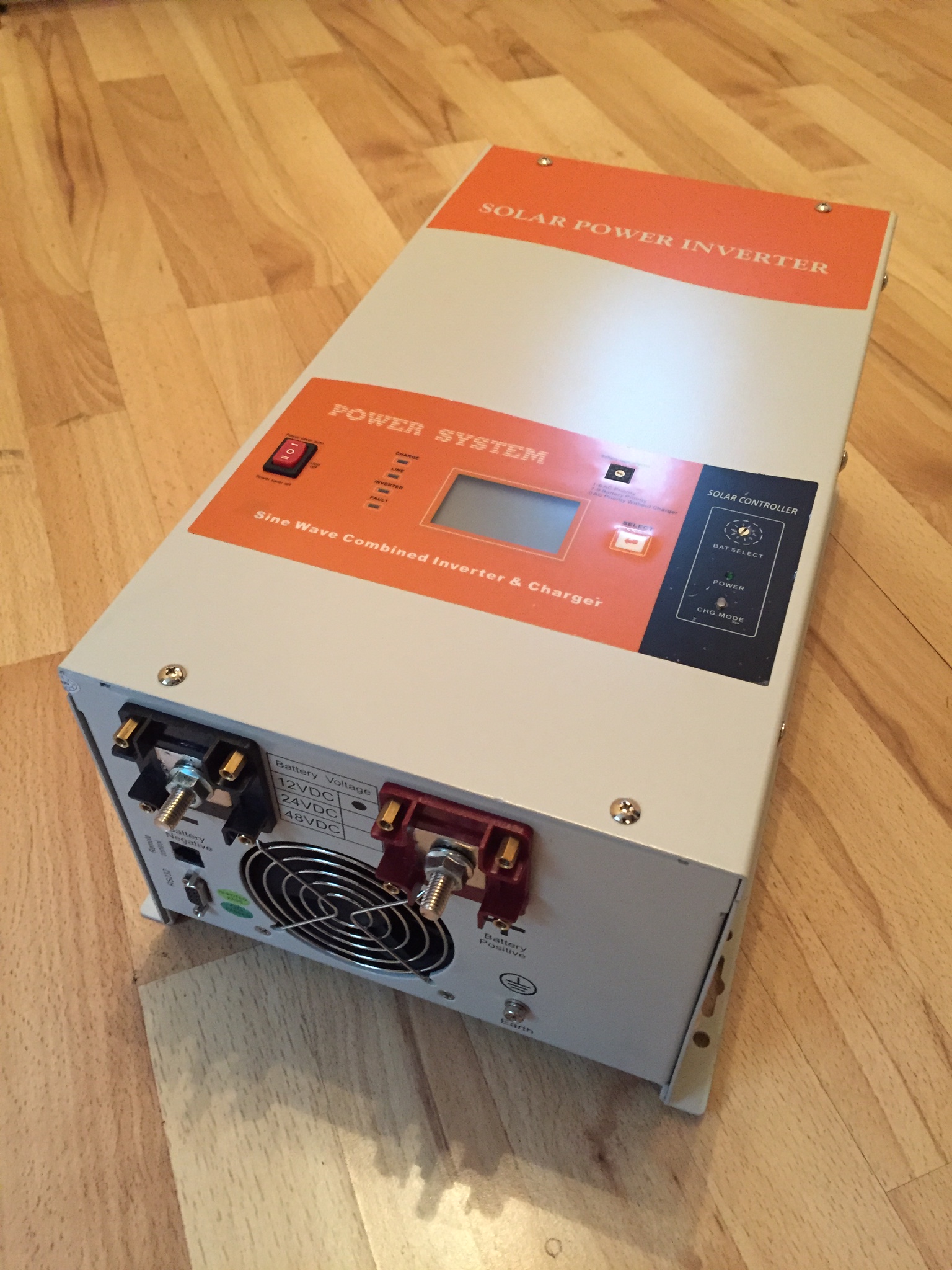
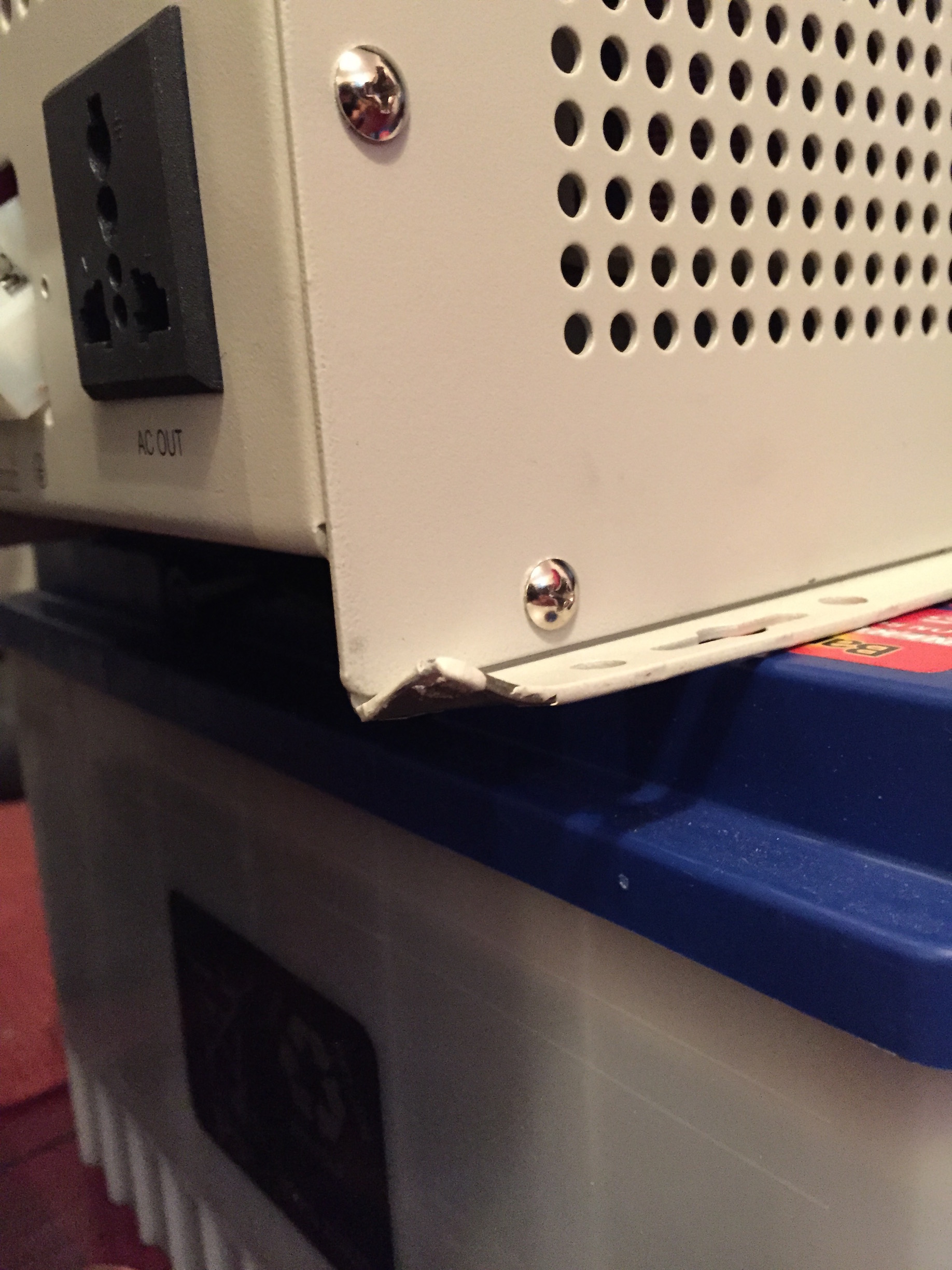
Naturally, DHL dropped it at some point during the delivery (I suspect right outside my place, judging by the sheepish delivery guy) and I am now claiming compensation and/or a replacement unit, even though this one appears to be working OK.
This unit charges the batteries from either the mains supply or from solar panels and provides 230V pure sine-wave output to power the appliances in the vehicle. It has a remote connection via a 6-pin RJ12 (6P6C) socket to a latching switch with LED (more on this below) as well as an RS232 connection which interfaces to unit with the popular WinPower UPS software available for most operating systems.
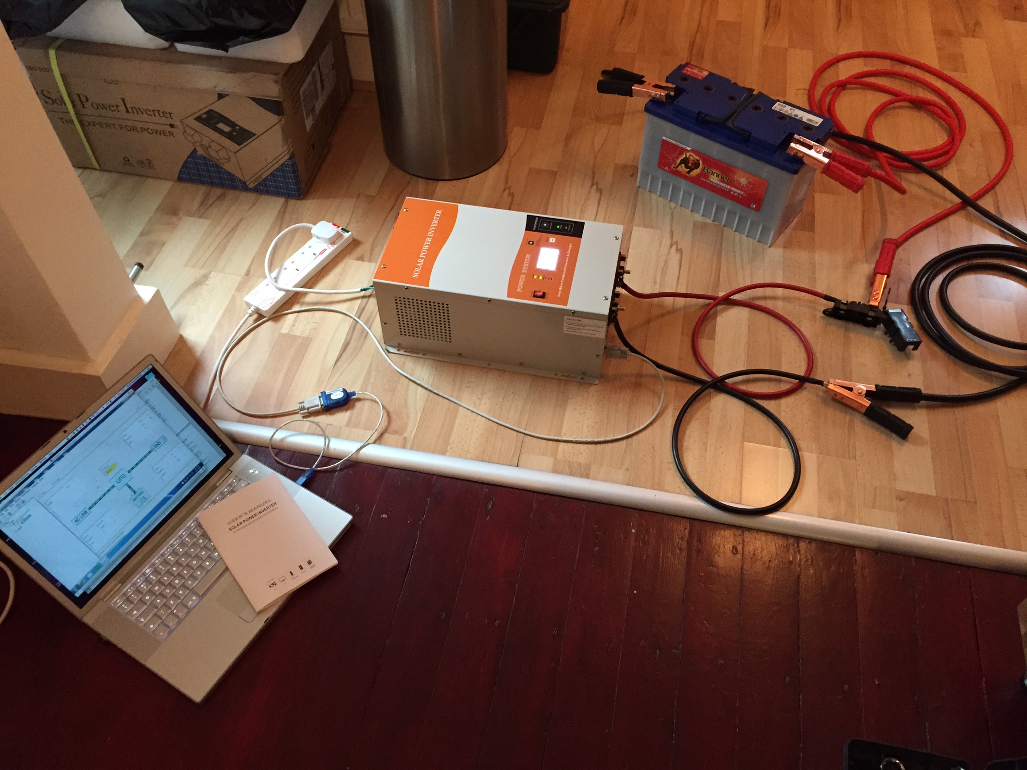
A quick "bench test" of the unit using the floor as a poor man's bench, some jumper leads and one battery.
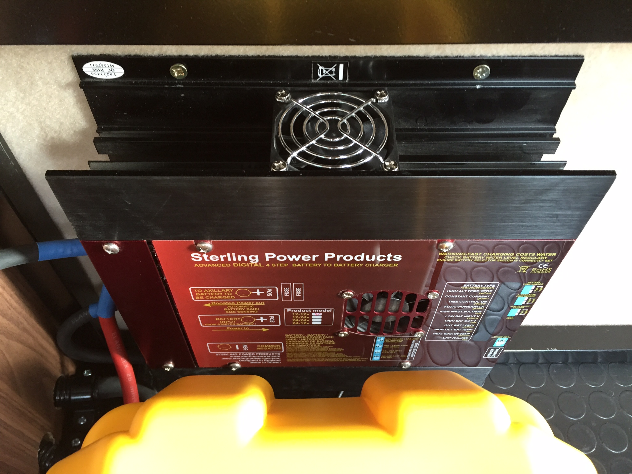
For when the vehicle engine is running, the domestic battery bank is charged via a Sterling BB1250 battery-to-battery (B2B) charger. This unit diverts maximum power from the alternator to charge the domestic batteries as efficiently as possible. To prevent damage to the alternator, the unit has a temperature probe connected to the alternator post and cuts out if the later reaches 100 C. The installation manual describes all of this in detail.
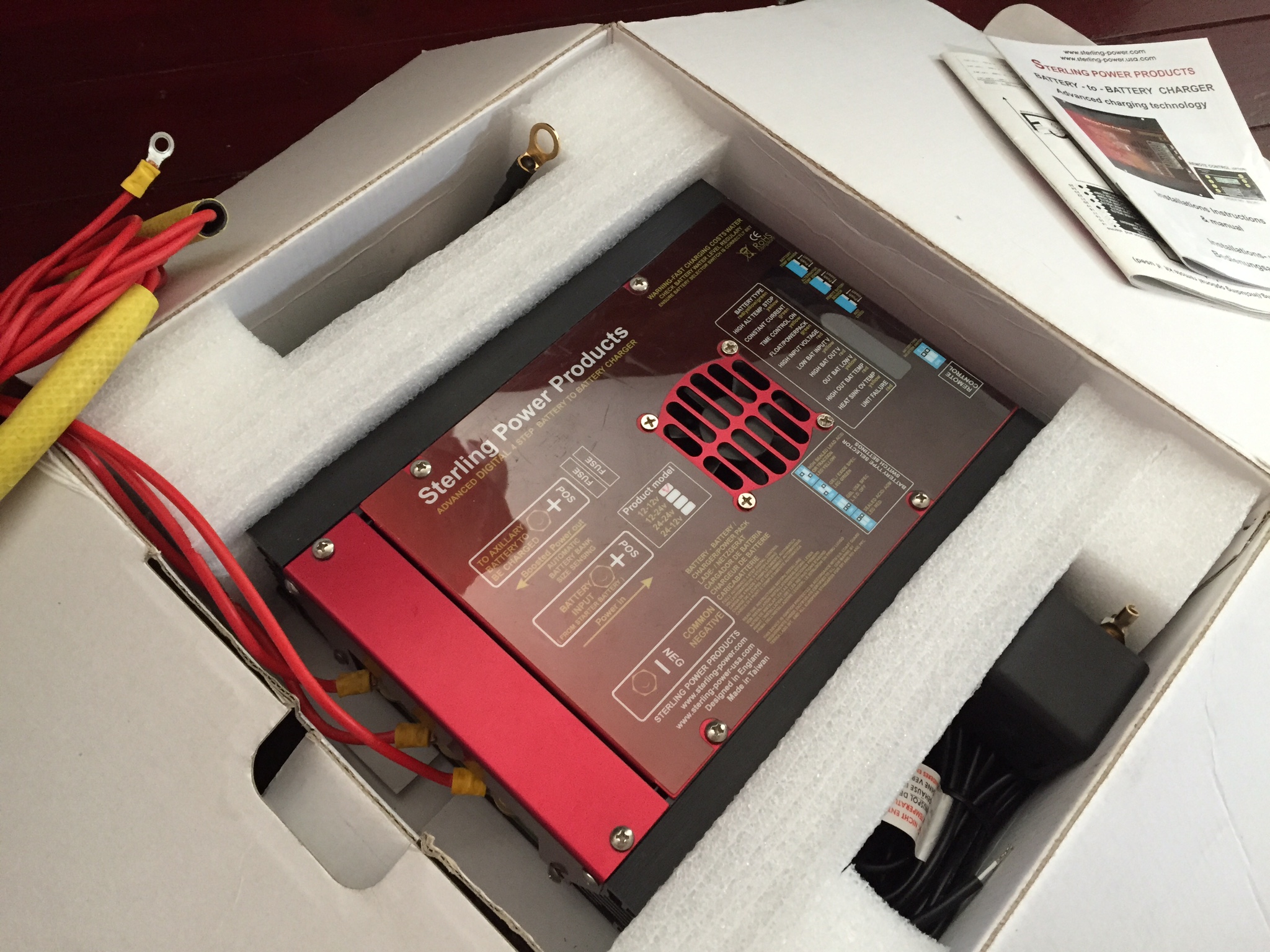
I was lucky to find a second-hand unit for sale in Germany at a reasonable price, otherwise they cost around £300 new. I've also purchased a Sterling BBCRC remote control panel for it.
Batteries
If you ever find yourself agonising over the decision of buying a battery, just read this article from Sterling. As a result, I went for a standard open lead-acid battery, from one of the leaders in the field.
We are planning to camp off-grid when we can, so I bought a pair of 135 Ah Banner Energy Bull batteries from alpha-battery-man's eBay shop. By my back-of-a-paper-napkin calculation, these are about 2-3 times our power requirements, so plenty of capacity I guess..
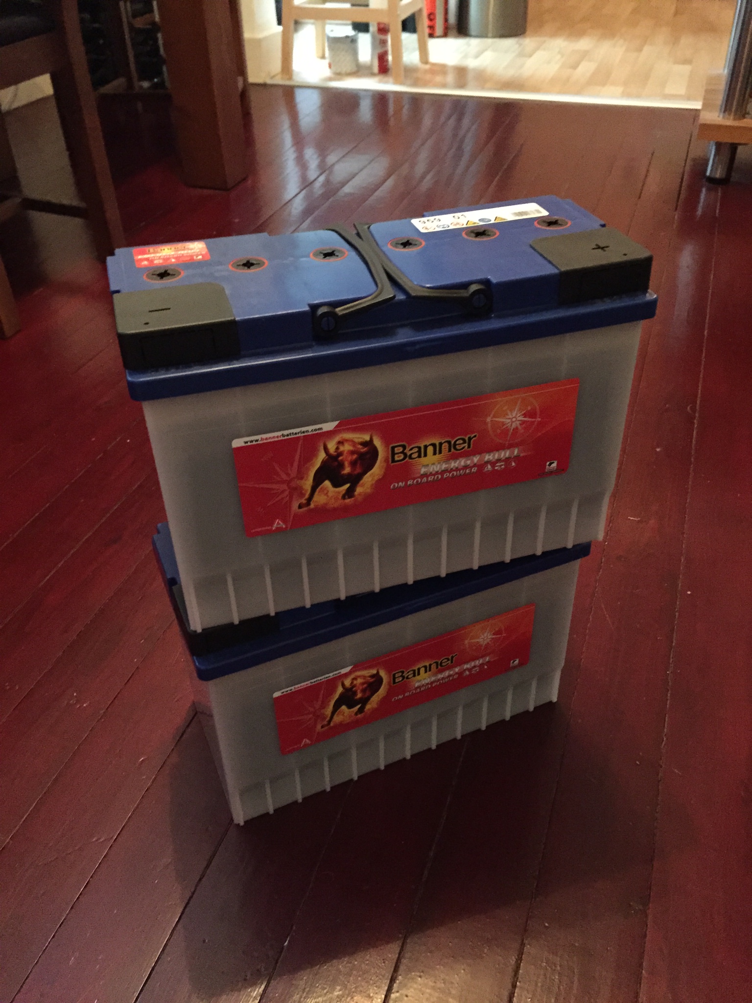
While these batteries are bit more expensive than the rest, they seem to be recommended more often than not by most sources close to the motorhome industry, which is good enough for us. As a side note, being an Austrian company with actual technical support, it enables one to obtain exact bulk/absorption and float voltages for these batteries, straight from the horse's mouth:
The charging voltages by 25°C of Energy Bull are:
Float: 13.5V
Cycle: 14V
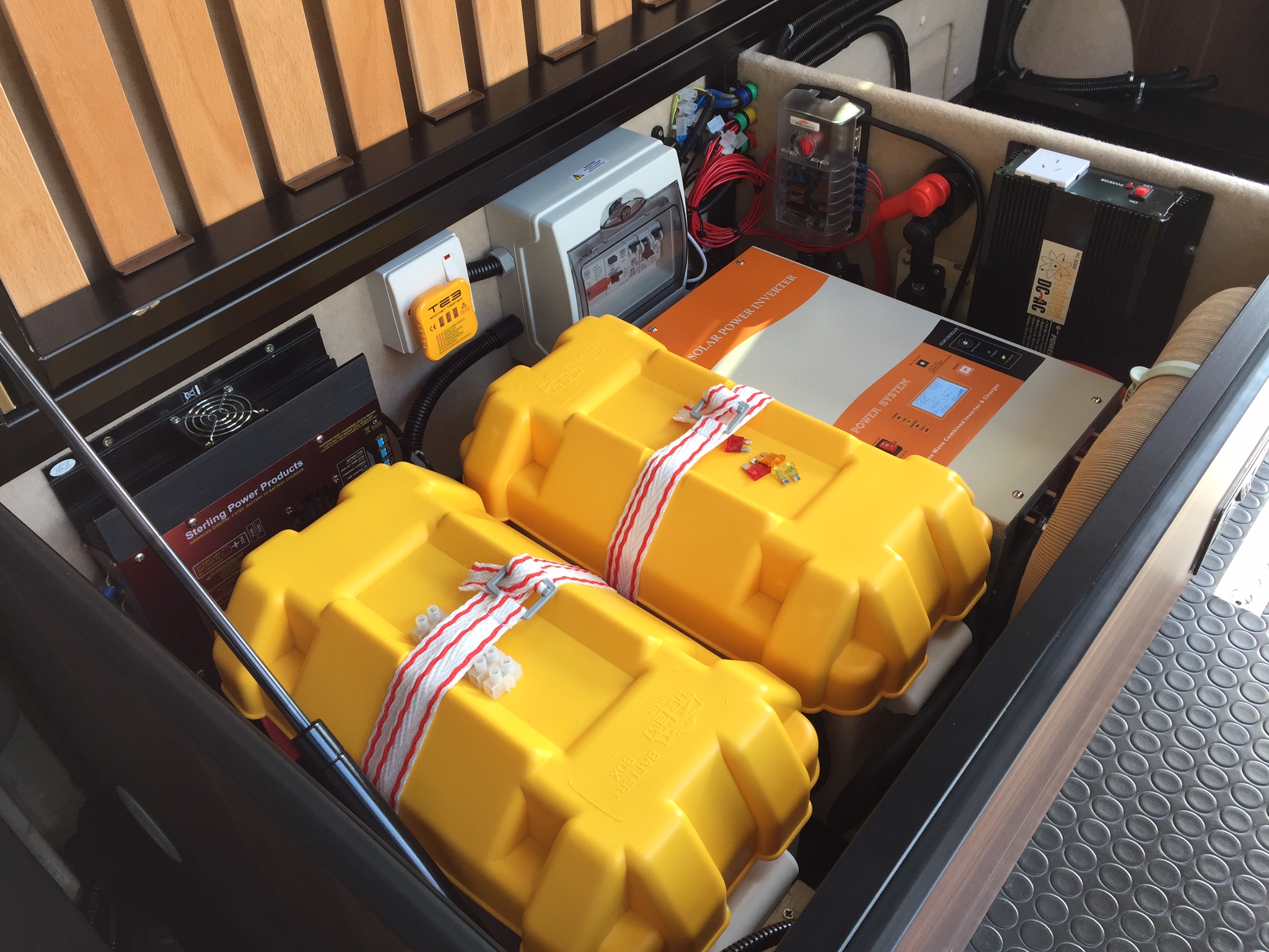
The batteries are housed in large Italian made plastic battery boxes from Midland Chandlers eBay shop.
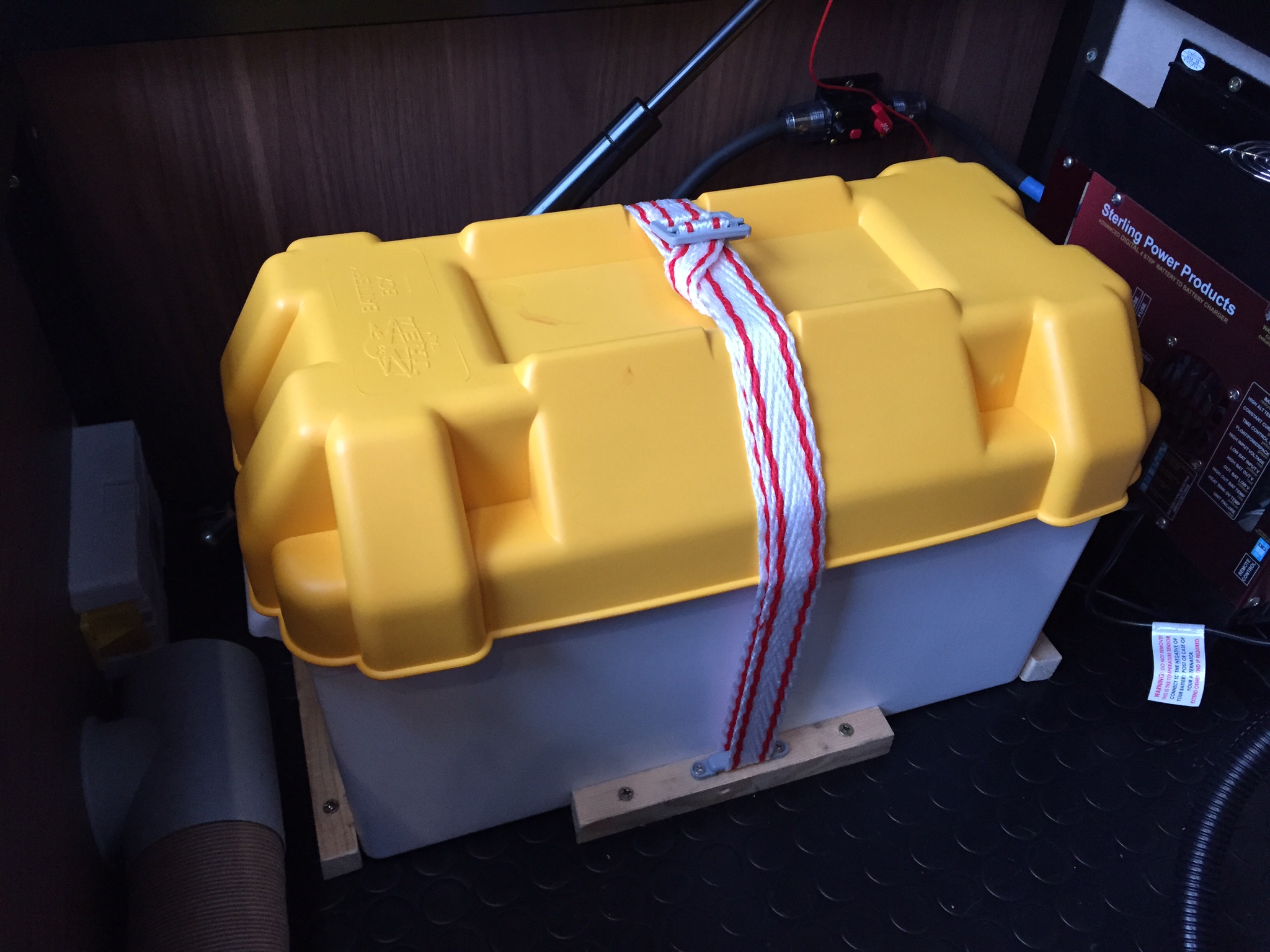
These boxes barely fit our batteries and the straps seem to be a bit weak, but otherwise they seem to be doing a good job. I've also put some timber stoppers all around the batteries to stop them sliding around.
12V DC Electrics
I am over simplifying here, but the main concepts to pay attention to when working with electrical stuff are:
Watt's Law(P = V*I), which I always remember it asWAV(Watts = Amps * Volts)Ohm's Law(V = I*R), which for practical purposes allows voltage drop calculations over longer cable runs- order more cable that you think you'll need (goes for everything else as well)
- avoid becoming the earth conduit (at least for AC)..
So for our 2000 Watt inverter, running at 12 Volts, the maximum current should be 2000 / 12 = 166.666 Amps. Although the inverter has a surge rating of 6000 Watts for very short periods of time.
Sterling recommend a cable with a cross sectional conductor area of 70mm2 for runs up to 1.5 meters for their 12V 2500W inverter. I just went with that for our inverter. For reference, these cables are around 15mm in diameter and don't tend to bend well in tight spaces.
For voltage drop calculations, the link above gives a calculator at the bottom, so you don't have to do the maths. For loads at and above 5A, you can also use the Sterling reference table to do the same. Battery charges and other electronic components relying of sensing accurate voltages are particularly susceptible to voltage drop, so generally it is a good idea to use thicker cables and limit the length as much as possible.
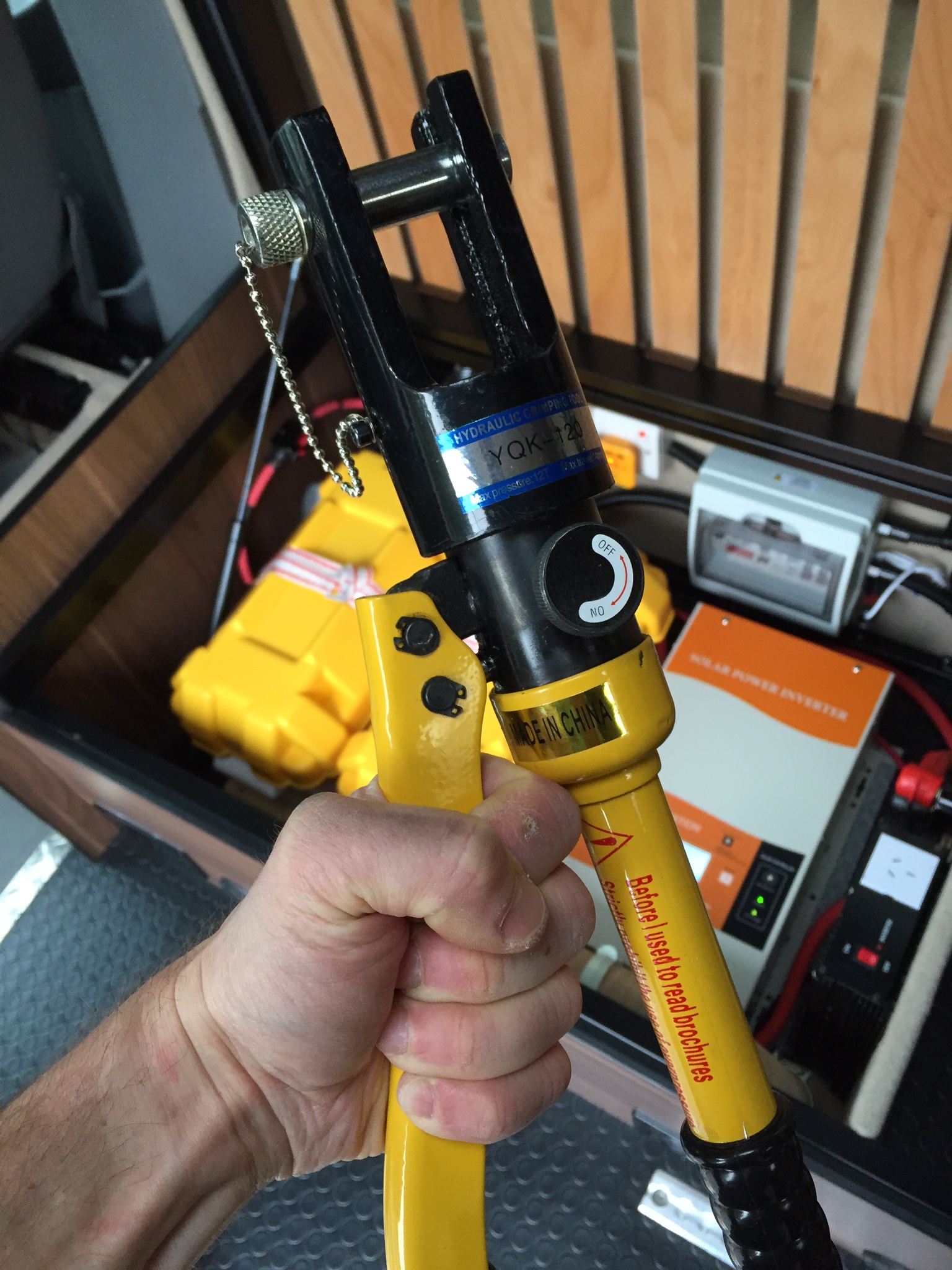
For the Sterling B2B charger and the SANTAK - EATON inverter/charger I used 25mm2 and 70mm2 cables respectively. Which brings me on another topic. I've crimped cables a few mm2 with pliers, but I can tell you that crimping a thick battery cable using the same approach is a different matter. You can of course bang your eylets with a hammer until they make contact or break, or spend £30 and get a cheap Chinese 12 Ton hydraulic crimper from eBay, which is what I've done.
Schematically, the 12VDC system looks like this.
Physically, all of the components occupy the first half of the bed box. I've made a partition from left over floor plywood and covered it in the left over carpet with the seam at the bottom and the sides of the panel.
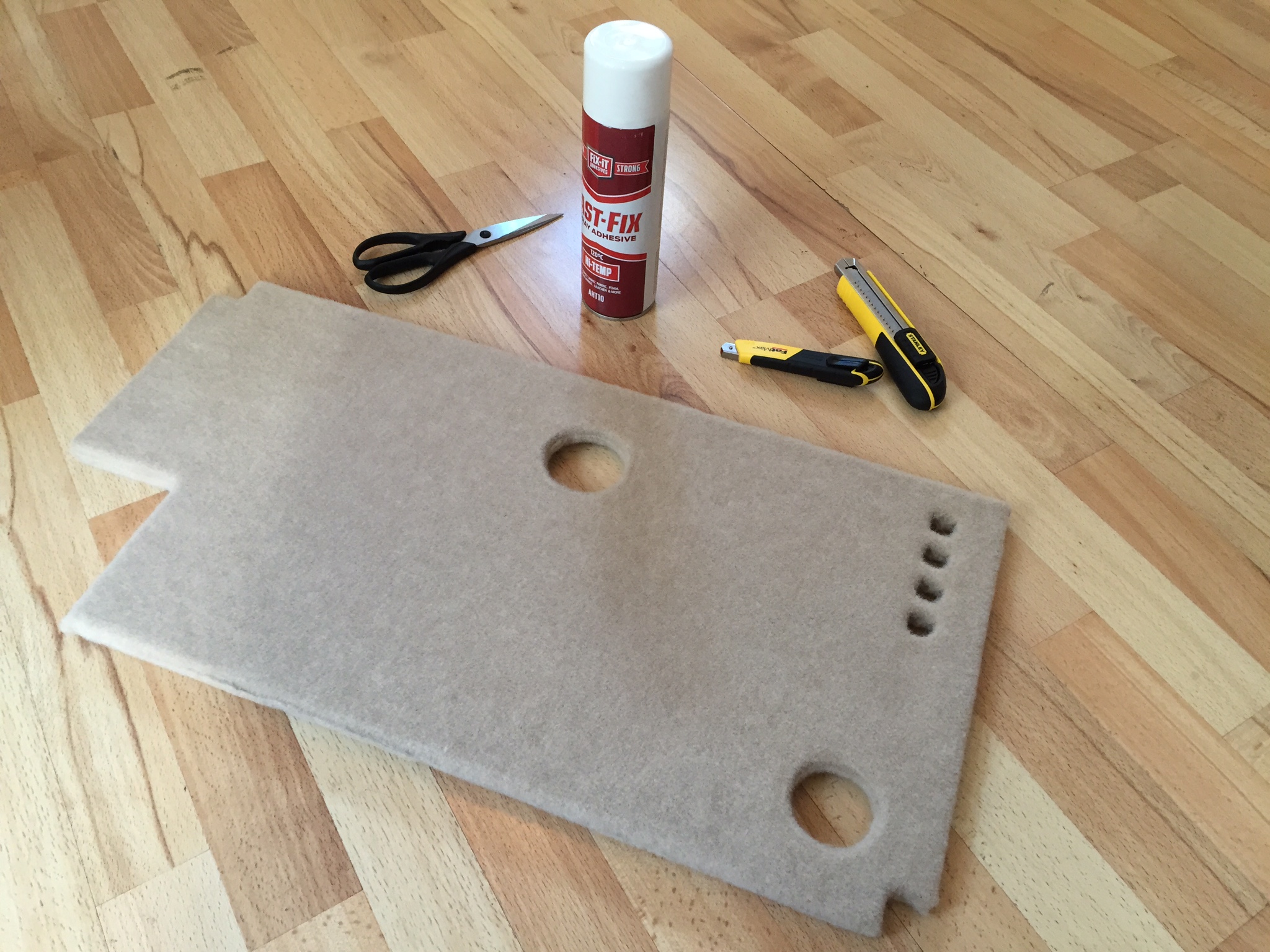
The system fits into the space fairly tightly, however I've cut out some ventilation holes in the side of the bed and the divider to hopefully get the air-flow going a bit.
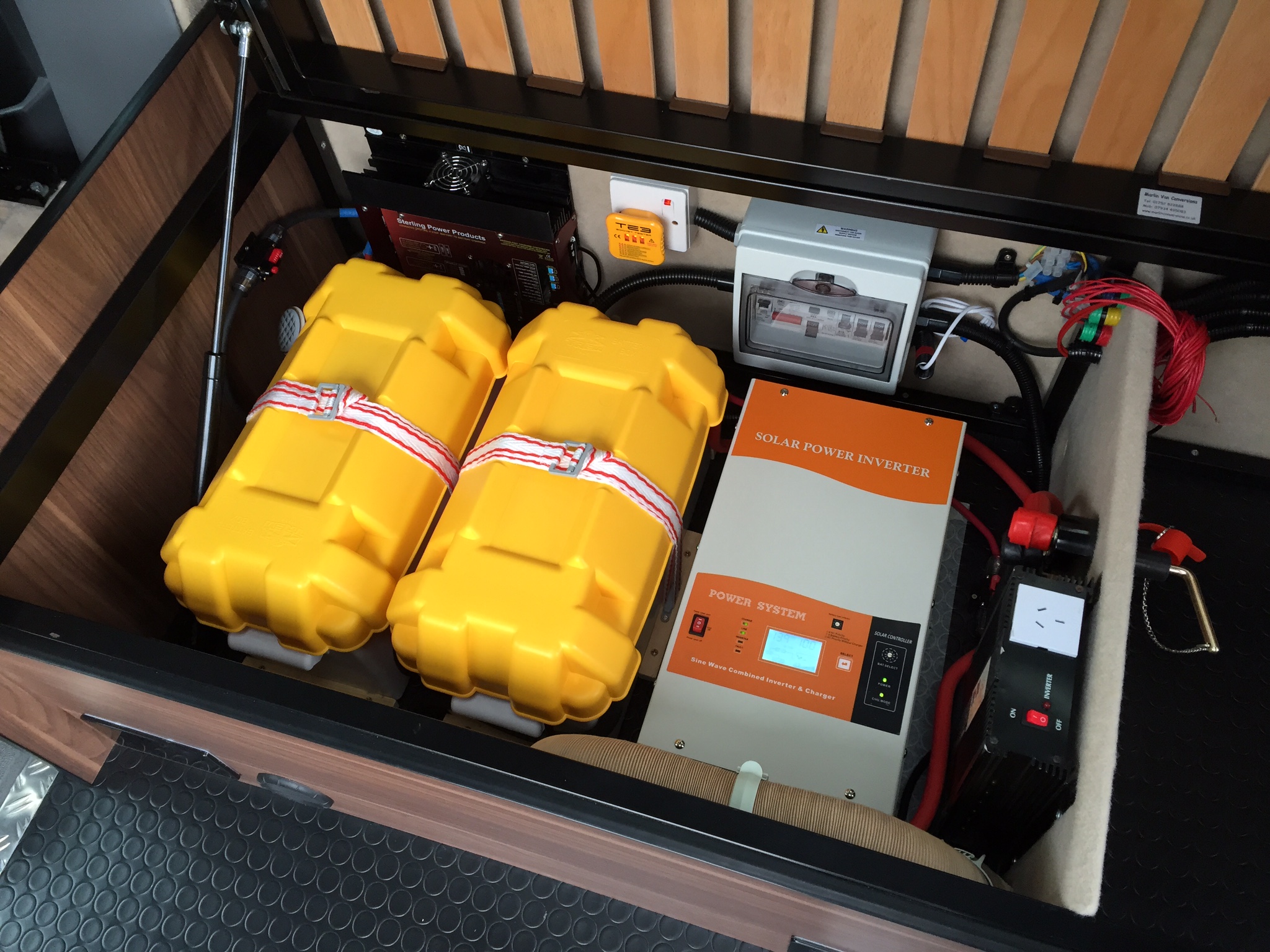
The centre piece of the installation is the already mentioned inverter as well as the B2B charger.
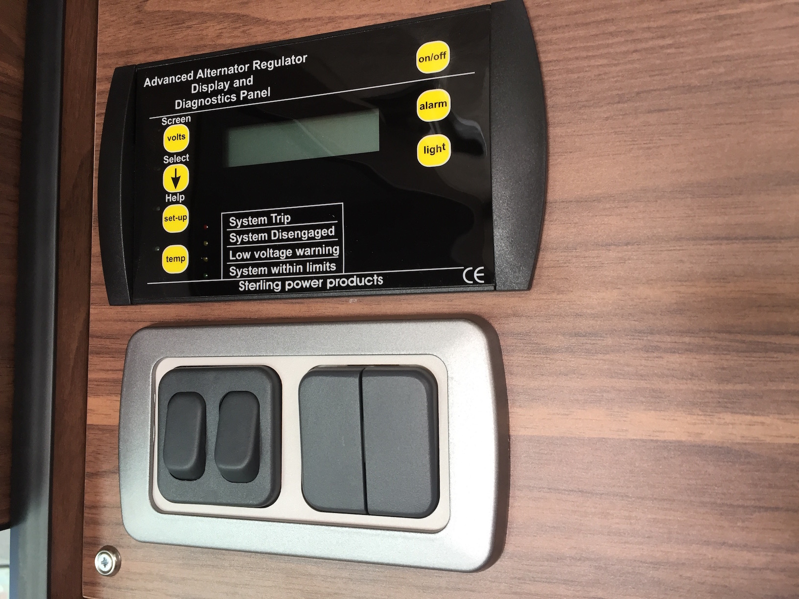
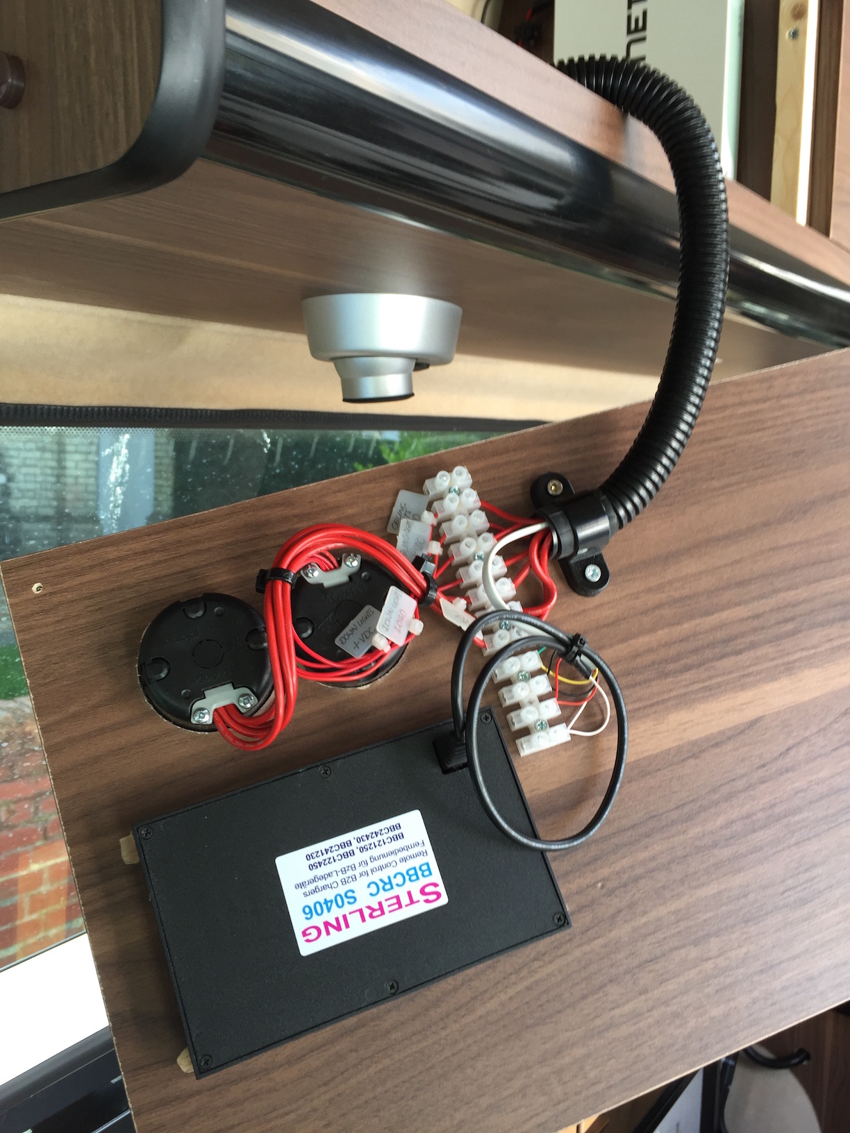
The remote control panel for the BB1250 is installed in the wiring closet above and behind the driver's seat.
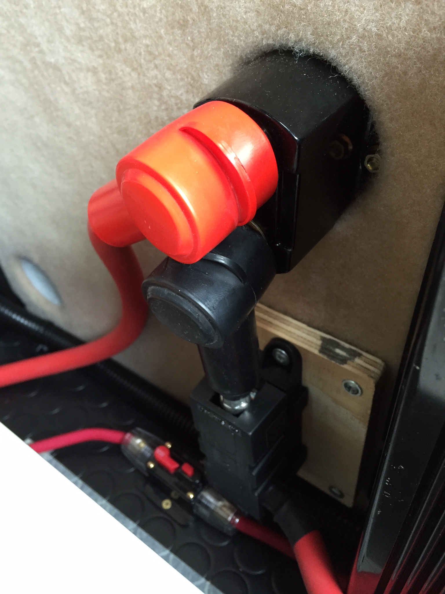
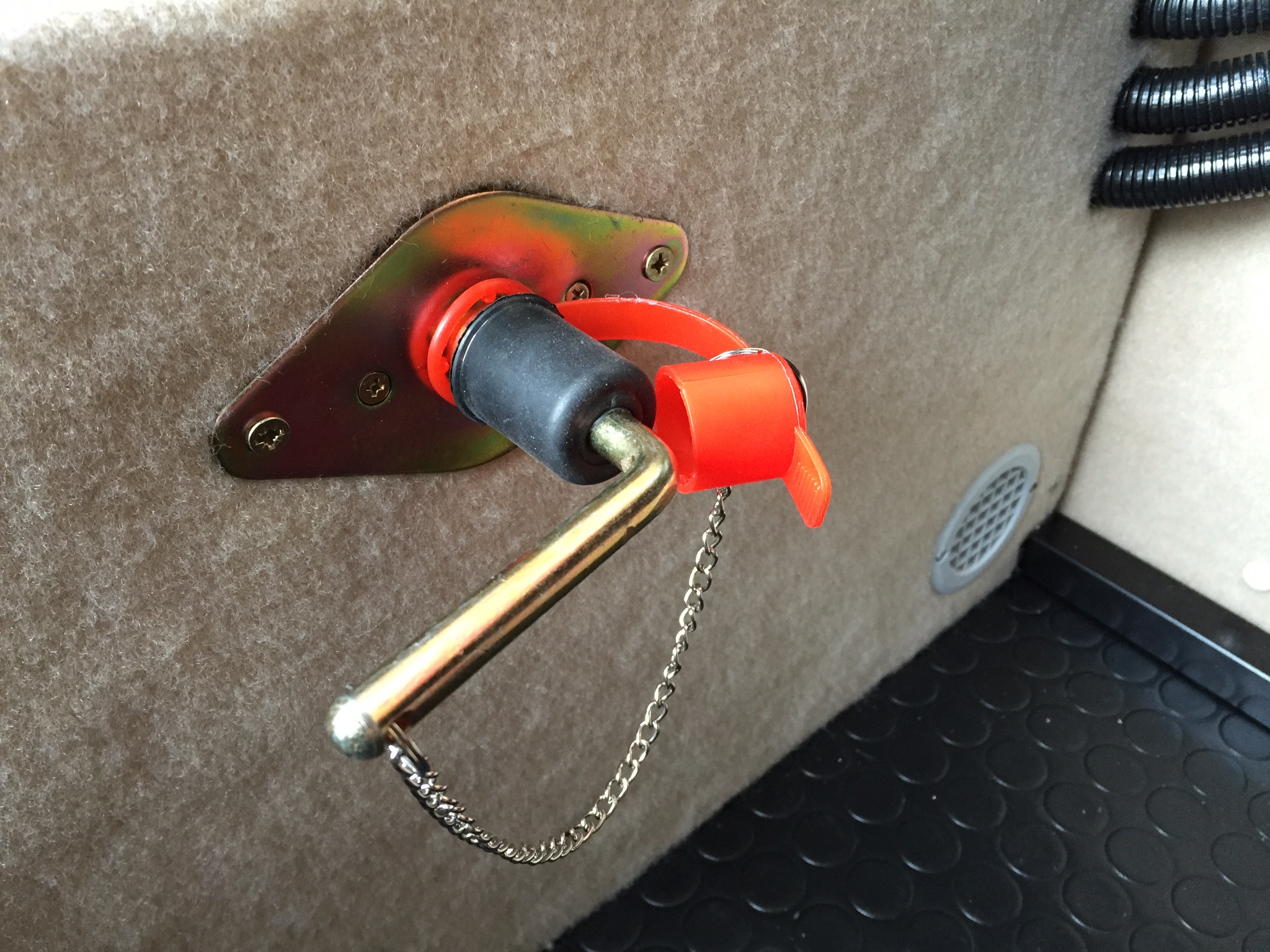
Some other notable components/features in the enclosure, include the 500A battery isolator switch and 400A mega fuse with fuse box.
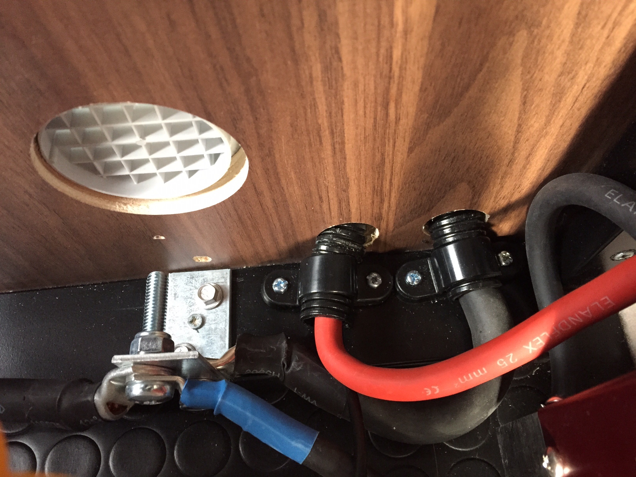
The common ground bus bar made from a galvanised bracket and terminated on a M10 seat post at the rear of the driver's eat (O/S) from which the paint has been sanded off to make a better contact. the bracket is fixed to the metal bed frame with Timco Classic C-1022 Steel Stitching Screws from Screwfix (rubber/metal washer removed for obvious reasons).
All of the 12V distribution to appliances is via a 12-way fuse box from
Simple Split Charge eBay shop. It has two separate feeds and lots of common ground points. I've used a 60A car audio/amp style circuit breaker for each of these feeds, which you can sort of see at the bottom.
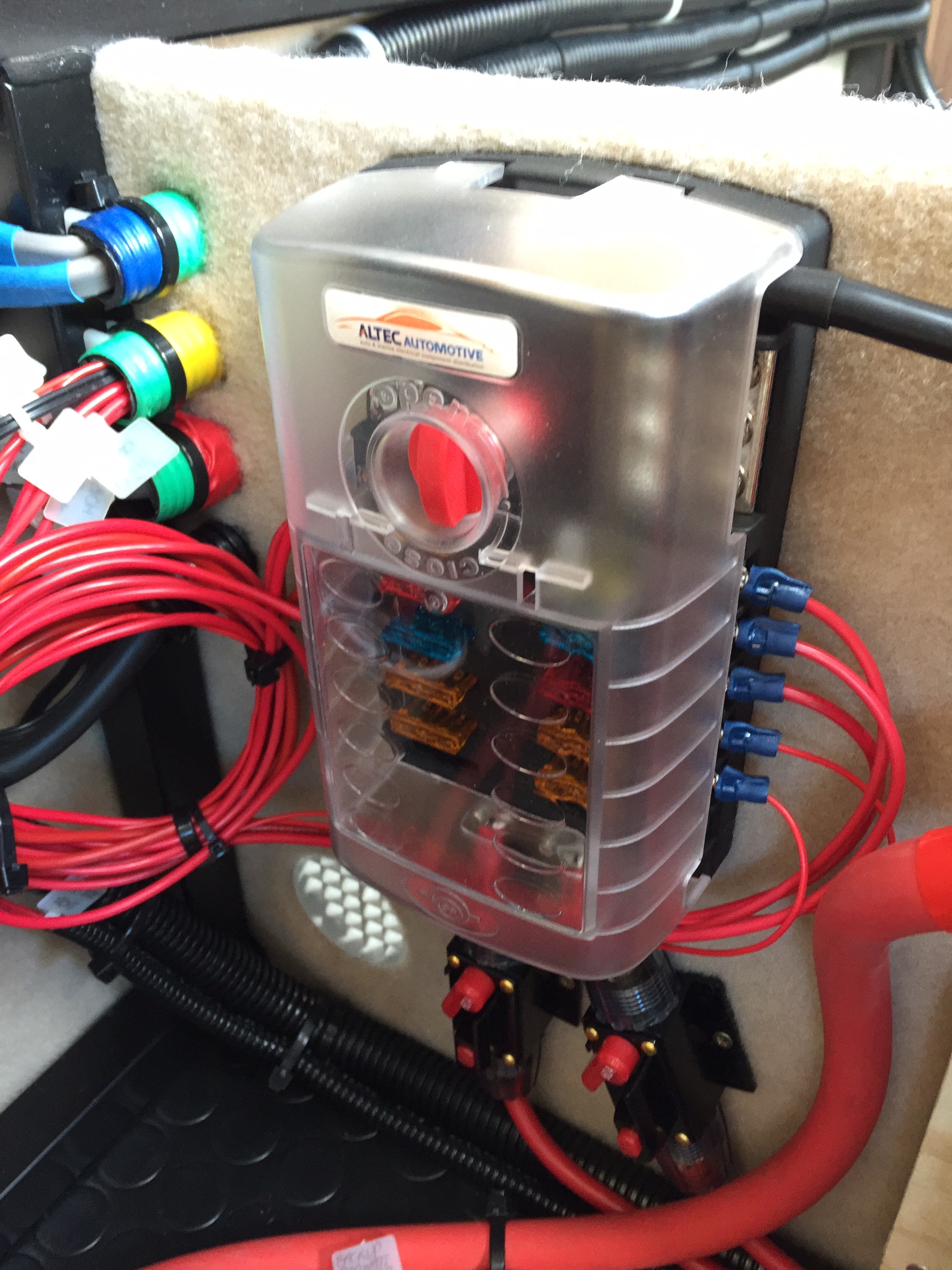
The fuse box is configured as follows:
- hob (
5A) - pump (
20A) - boiler (
10A) - fridge (
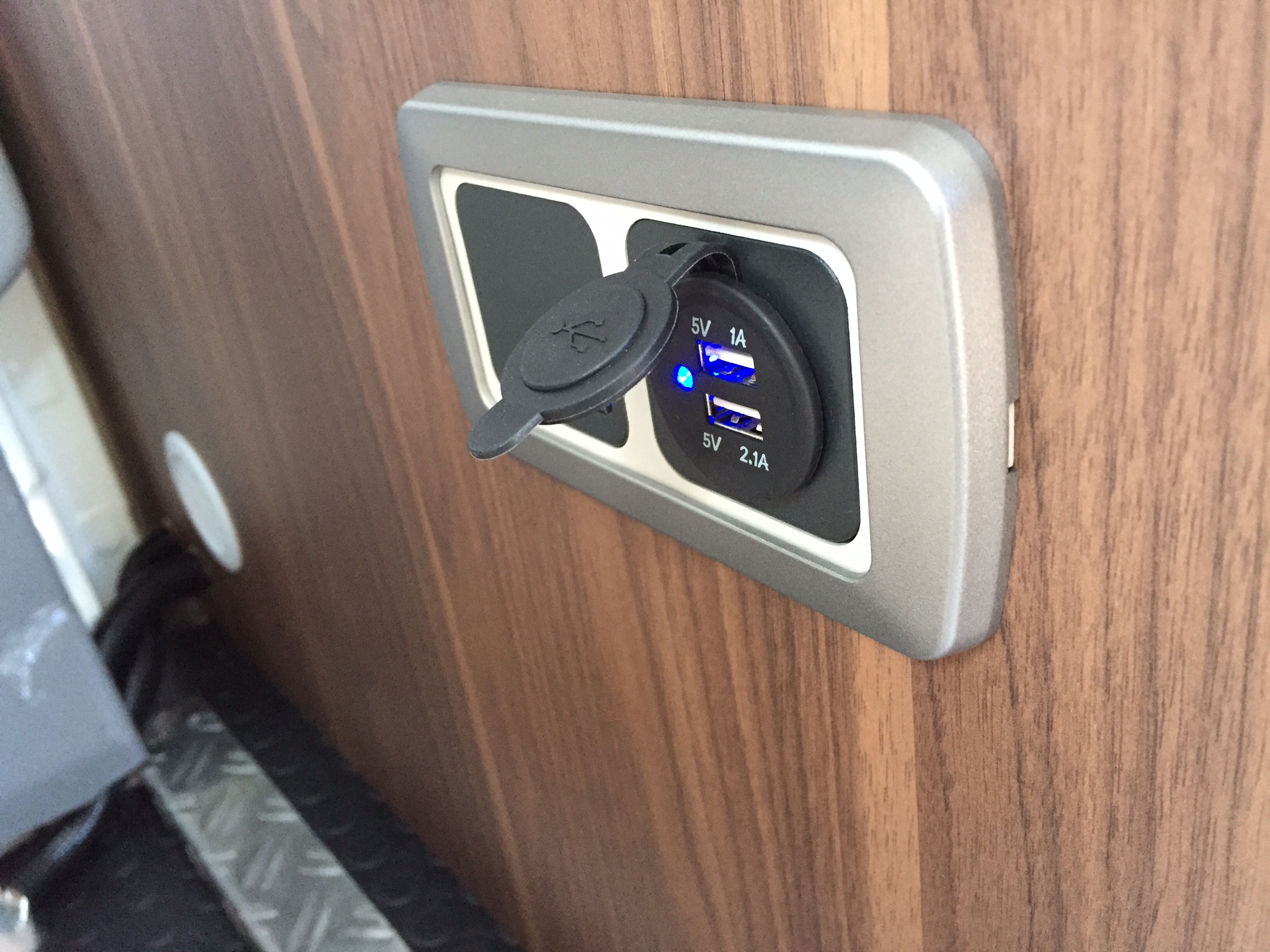
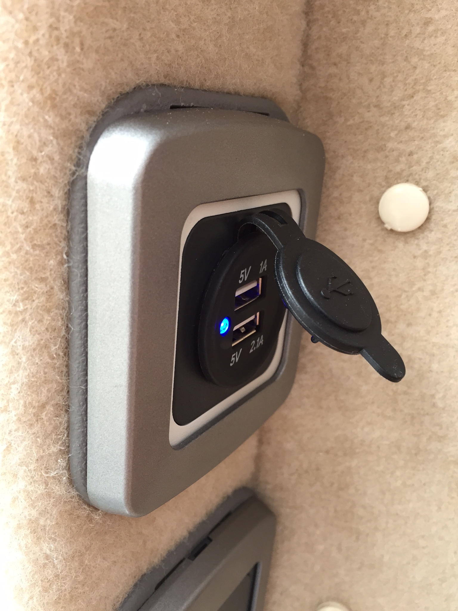
15A) - USB sockets (
10A) - tank heaters/defrosters (
10A) - 12V socket (
15A) - N/C
- wiring closet switches (
10A) - gauges and drain valve (
5A) - lights (
5A) 2.5mm2cable spare to wiring closet above bed (N/C)
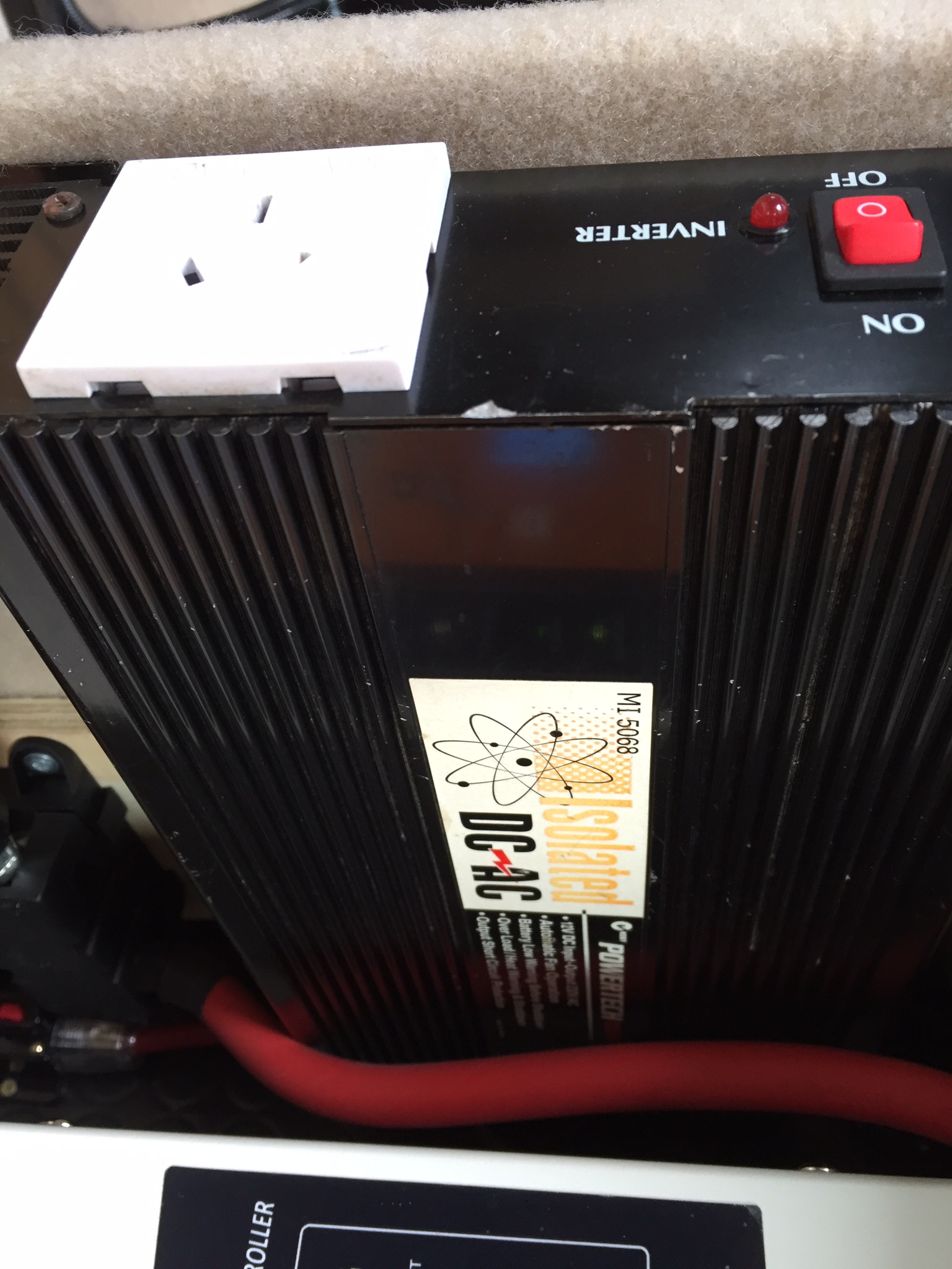
Finally, in case the primary inverter dies and we need to run the coffee machine, I've installed a Master Instruments emergency modified sine-wave inverter, which I've brought from Australia 8 years ago and haven't used since. This one is also protected by a car/audio style breaker, rated at 80A.
Grounding
To be honest, I had questions about where to ground all those black wires. Unlucky for me, having started reading forum posts by what appear to be mostly untrained individuals, I was becoming a little anxious, having chosen to use the vehicle chassis as the common ground rather than running a separate ground to each device. Luckily, the following two articles cleared any doubts as to my chosen approach:
The summary is: for anything with a metal chassis sitting on rubber tyres, it is fine to use the chassis for all ground connections, as the tyres provide a high enough resistance to earth. For anything with a metal hull floating in a body of water - return back to battery negative terminal using appropriately sized cables.
Since we are not planning to float in bodies of water, chassis ground works for me. If we find ourselves floating, then we have much bigger problems..
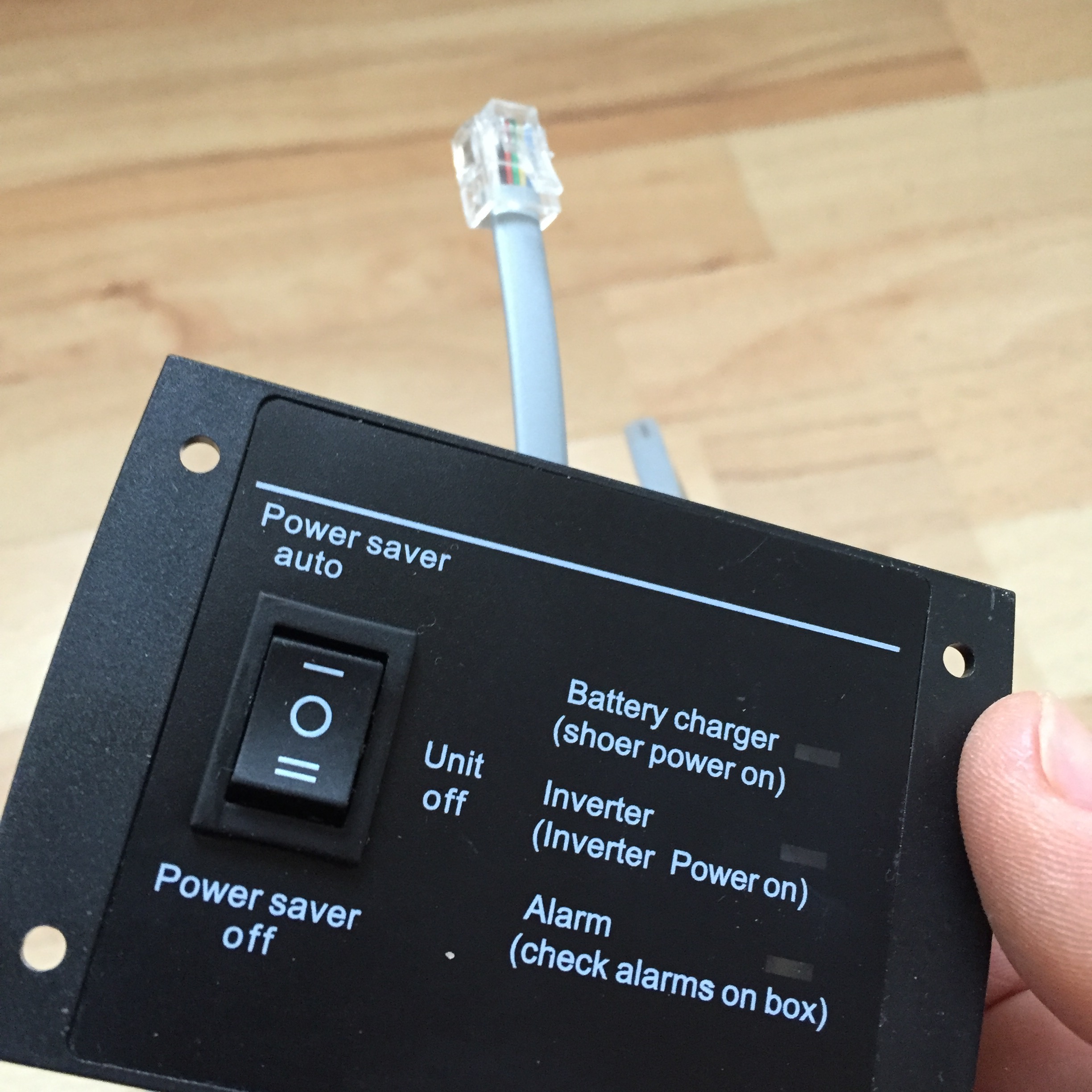
Inverter Remote Control
Our inverter has a standard 6P6C RJ12 port at the back, labelled "Remote control".
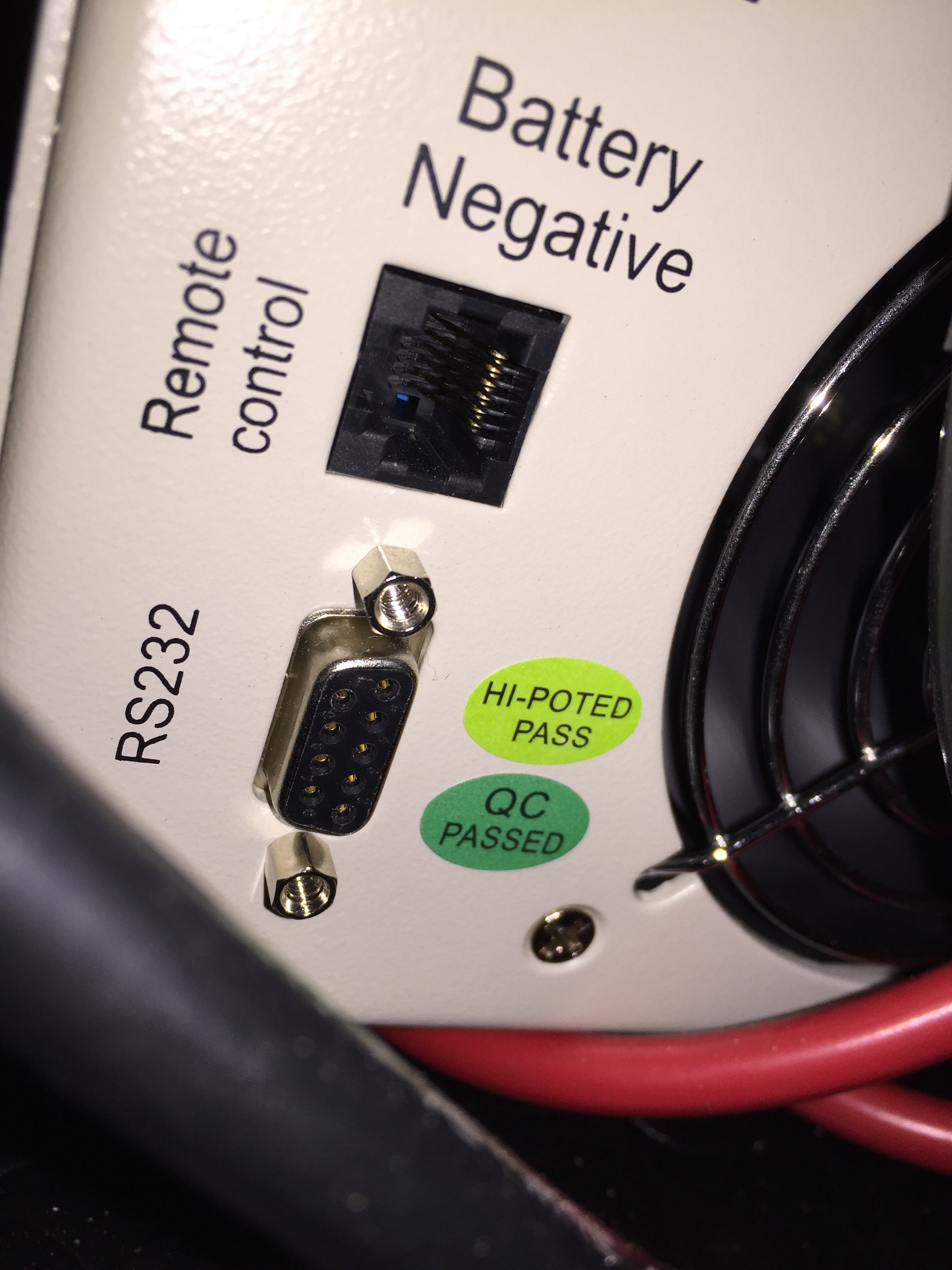
I couldn't get a response from the manufacturer on the pin-outs for this port, so as a test, I've ordered and plugged in a Remote power on / off switch for all low frequency inverters LK series supplied by Photonic Universe (LK2000, LK3000, LK6000 models, 12V, 24V and 48V modifications) and it worked right out of the box, with the exception of the LEDs.
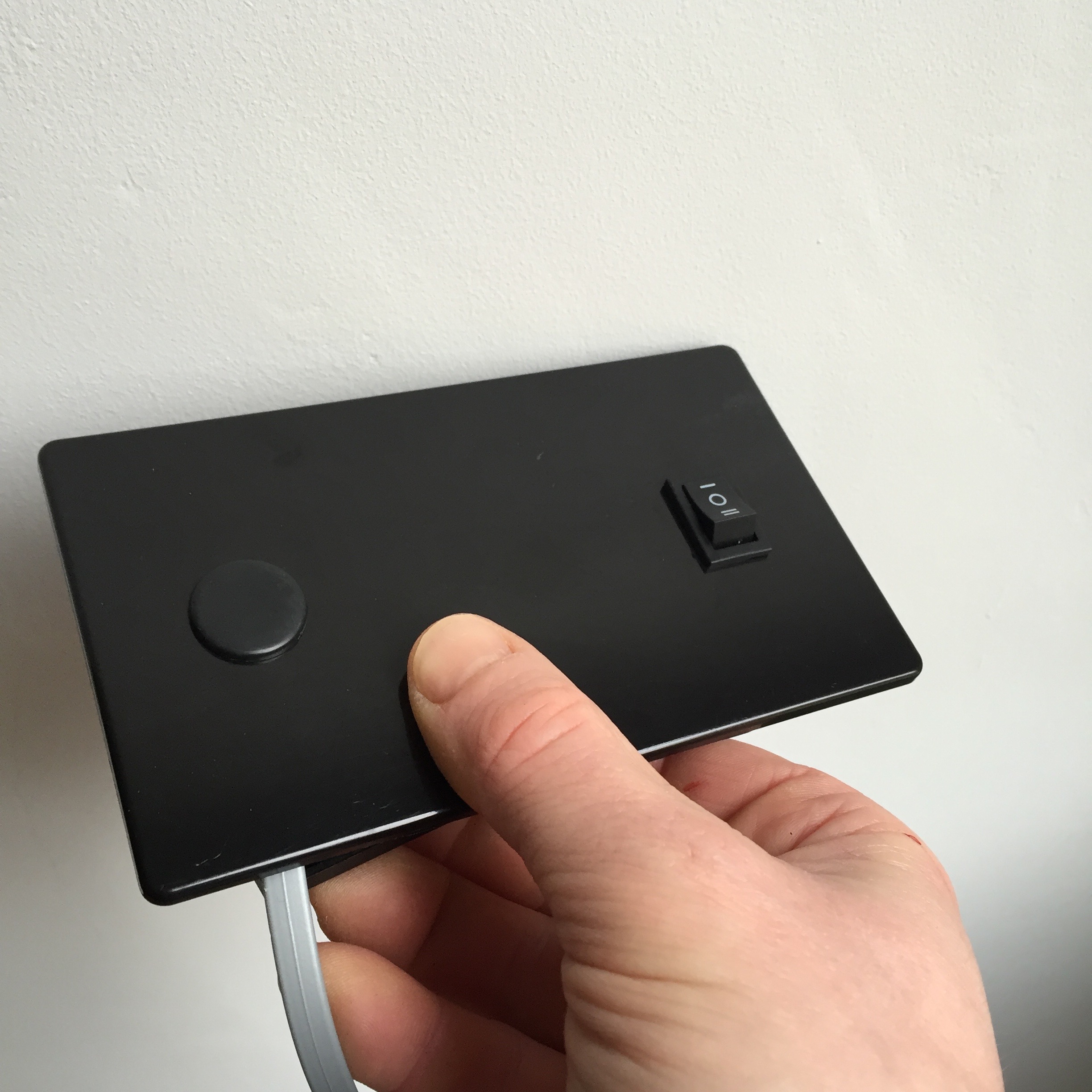
I am now able to cover up the previous fail of installing a 2-gang socket behind the table leg..

.. by replacing it with a 2-gang blank and mounting a two-way switch from the remote panel on it.
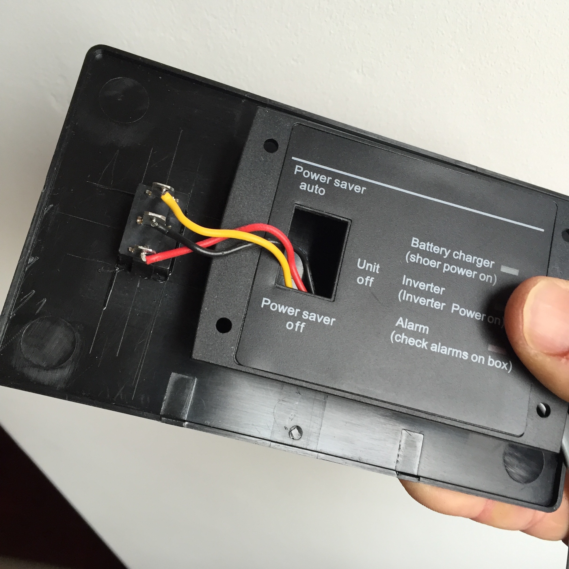
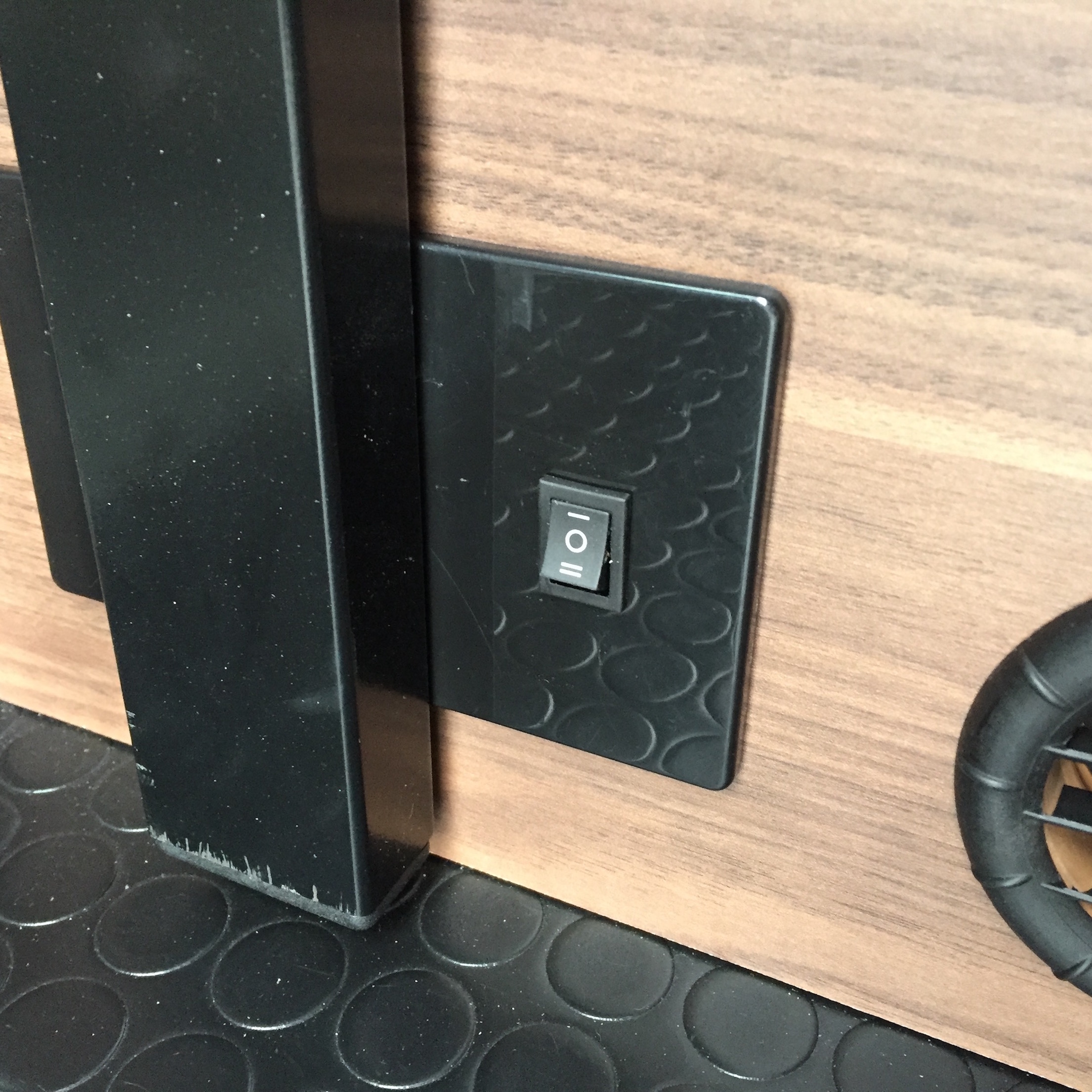
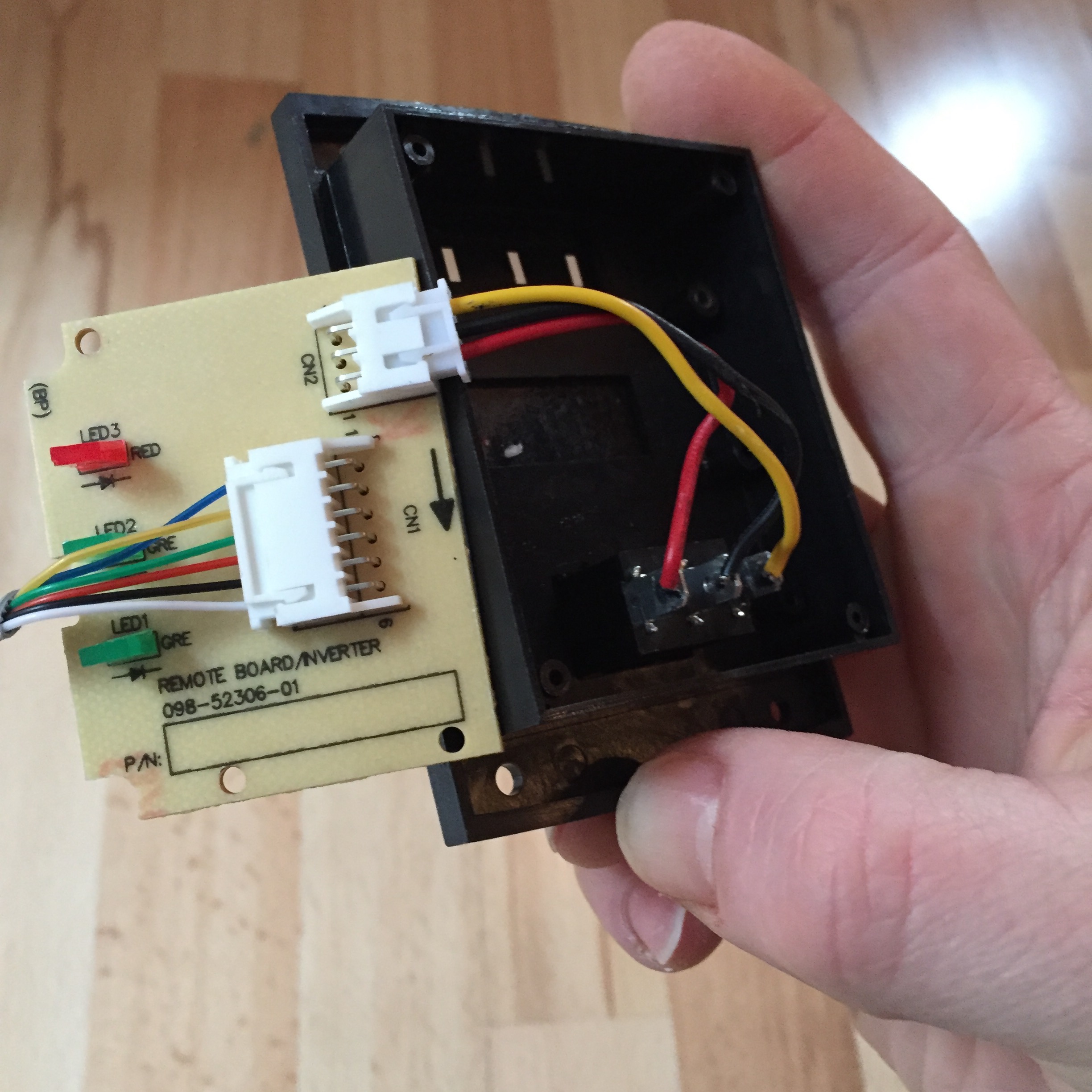
Had I known the pinouts, rather than buying the remote control panel for £14, I could have just bought a 3-way rocker latching switch 12VDC and wired it as follows:
RJ12 - 3-way rocker latching switch 12VDC
-----------------------------------------
pin1 - inverter on, power save off (II)
pin2 - common (O)
pin3 - inverter on, power save auto (I)
pin4 - NC
pin5 - NC
pin6 - NC
Note, in "power saver off" mode, the inverter supplies 110/240VAC to output even if there is no load. In "power save auto" mode, the inverter only supplies VAC to output if it detects load. The latter mode isn't compatible with some types of loads.
Lights, Sockets and Appliances
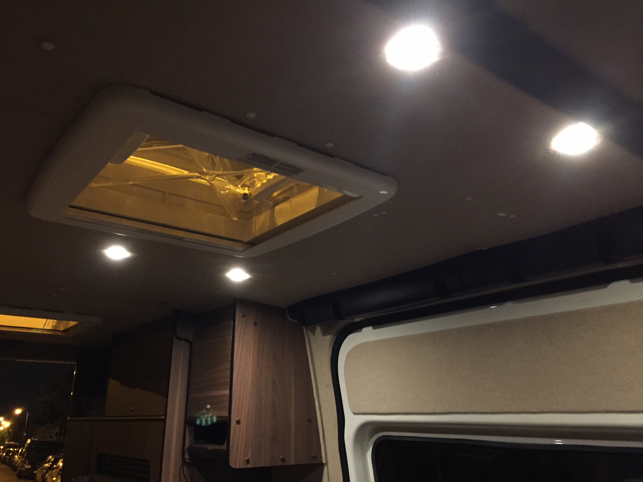
With the 12V electric hook-up completed, we now have lights, USB charging as well as a cold fridge..
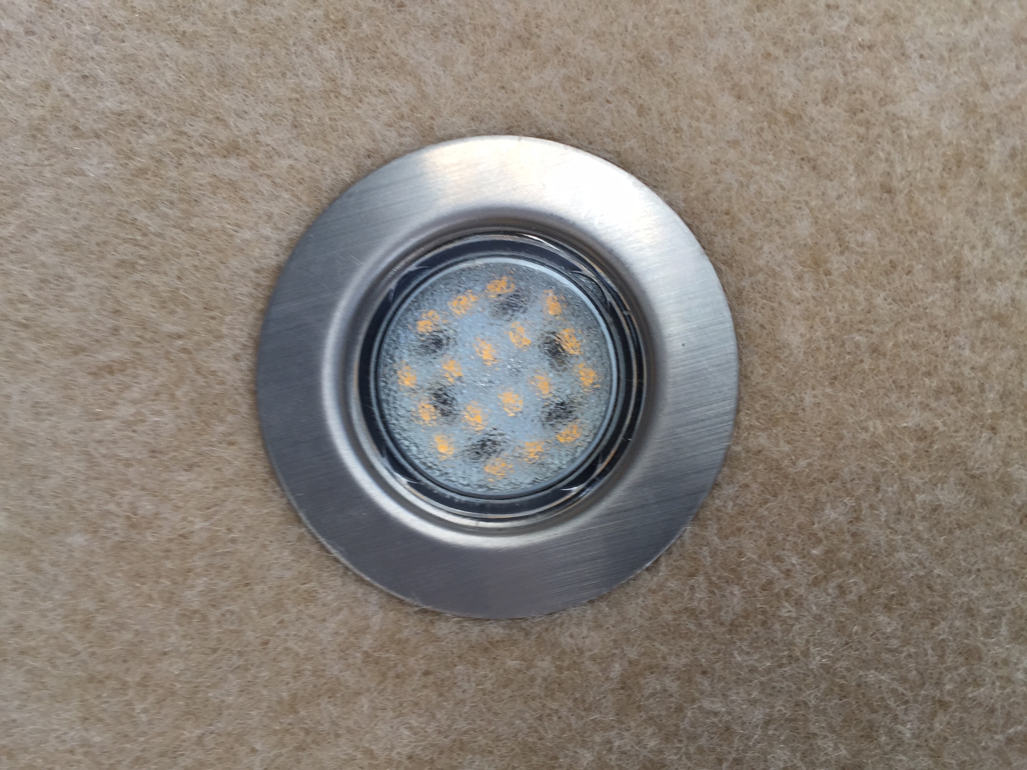
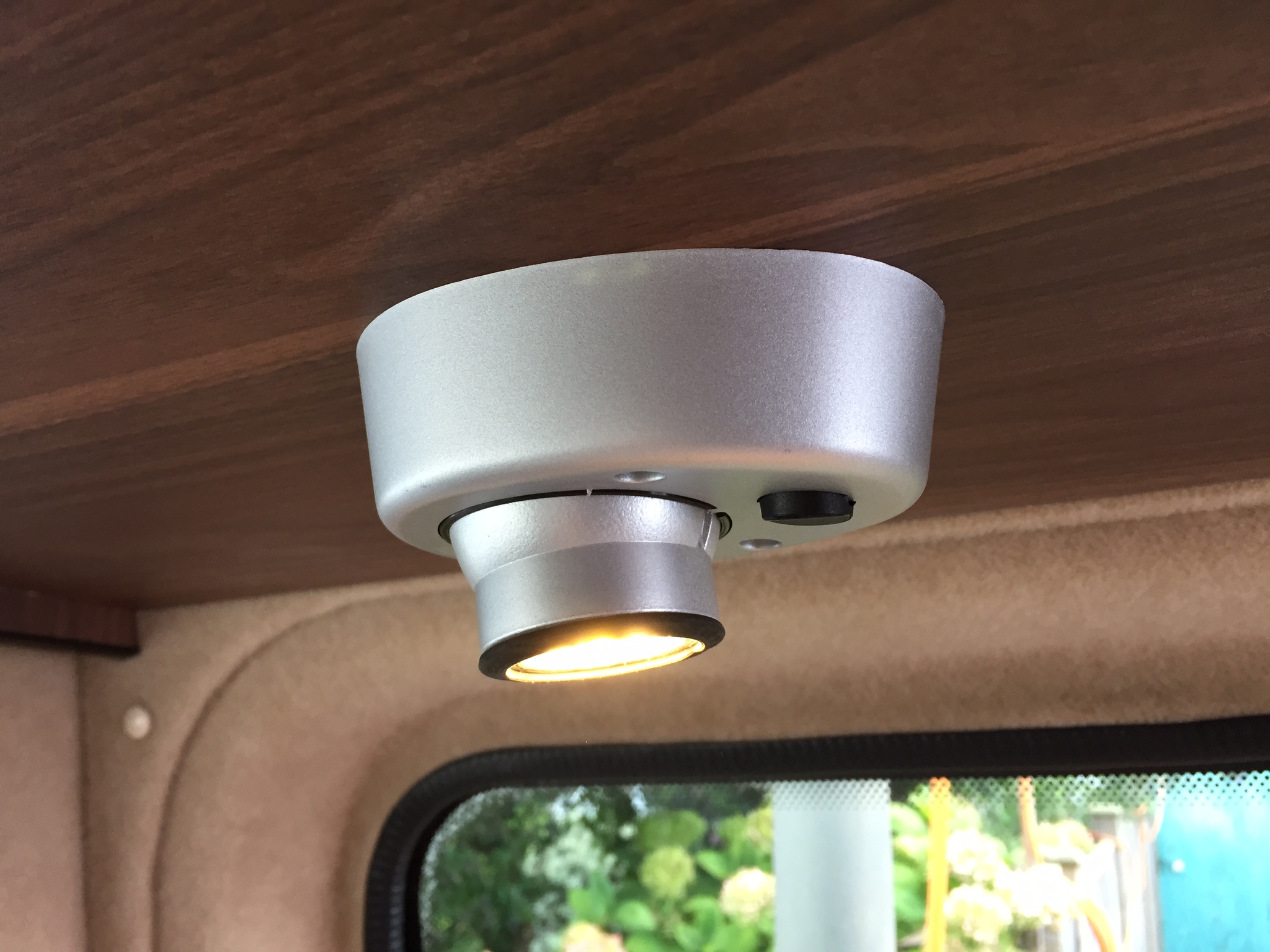
We installed Vega 48 LED lights for ceiling and down-lights in the cabinets.
I covered the 40mm holes for the down lights inside the cabinets with some cheap Chinese 40mm rubber grommets (again from eBay). Since the thin membrane tore immediately, I ended up flooding the grommets with black Sikaflex and running the wires down a length of 10mm unsplit convoluted sleeve/conduit, secured with cable ties and small plastic saddles.
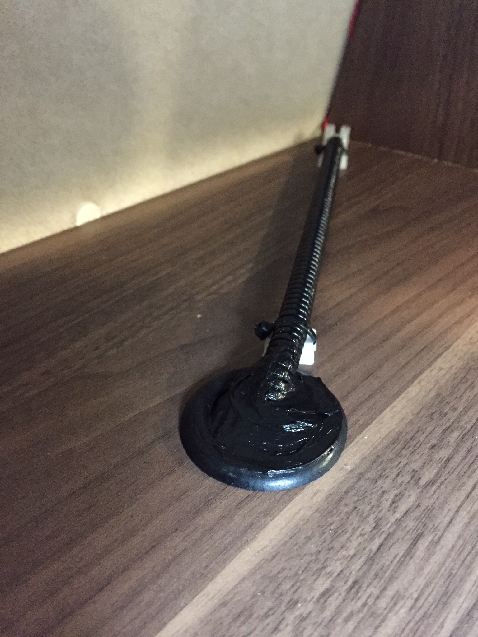
I made a mistake of not wearing gloves once when working with Sikaflex adhesive/sealant. My advice is not to do that, because that stuff doesn't wash off, period.
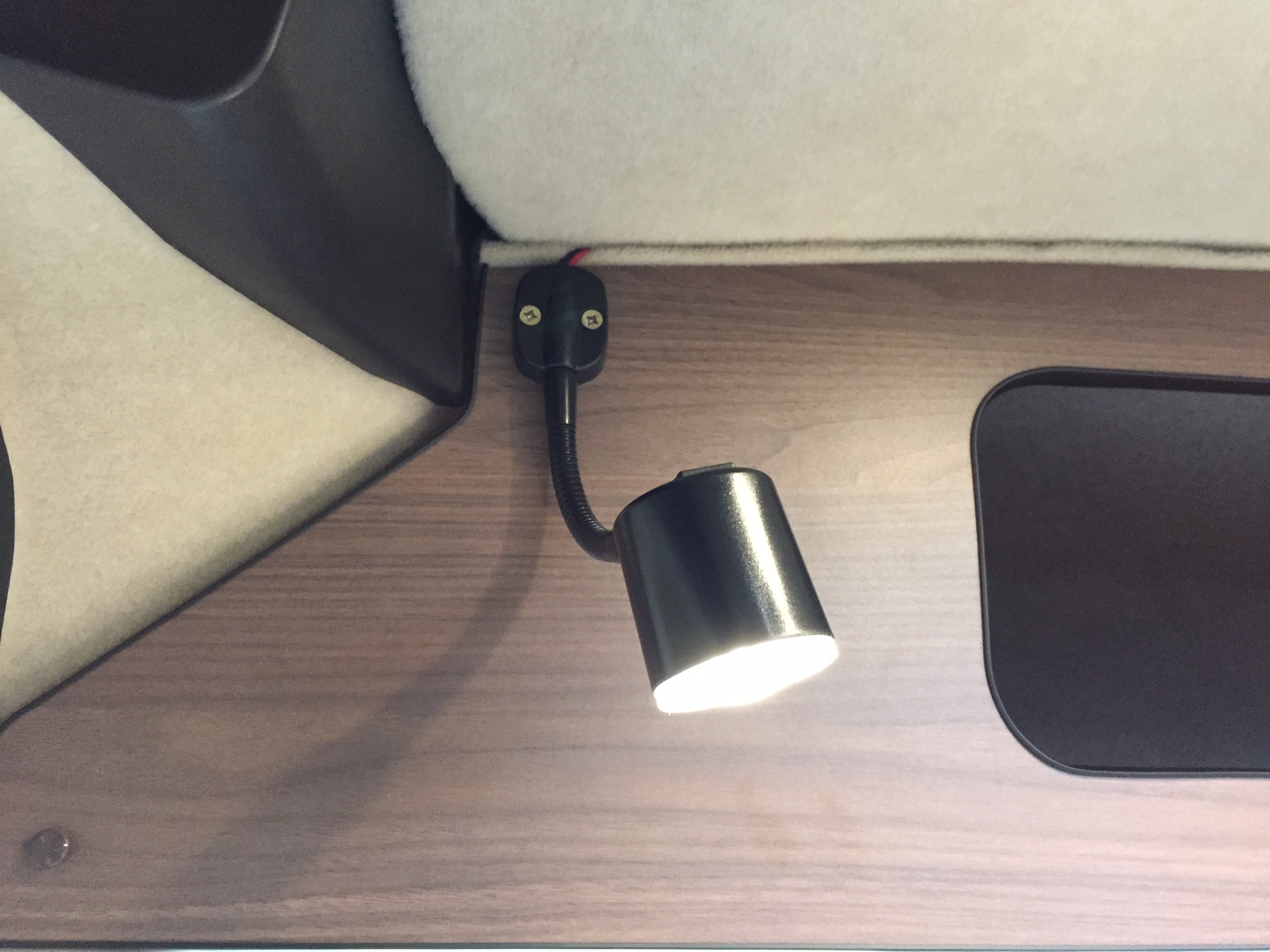
We also fitted a couple of reading lights Kurs and Eyelight. The Eyelight feels a bit cheap and is difficult to rotate. Maybe I'll get some silicone grease and see if that helps..
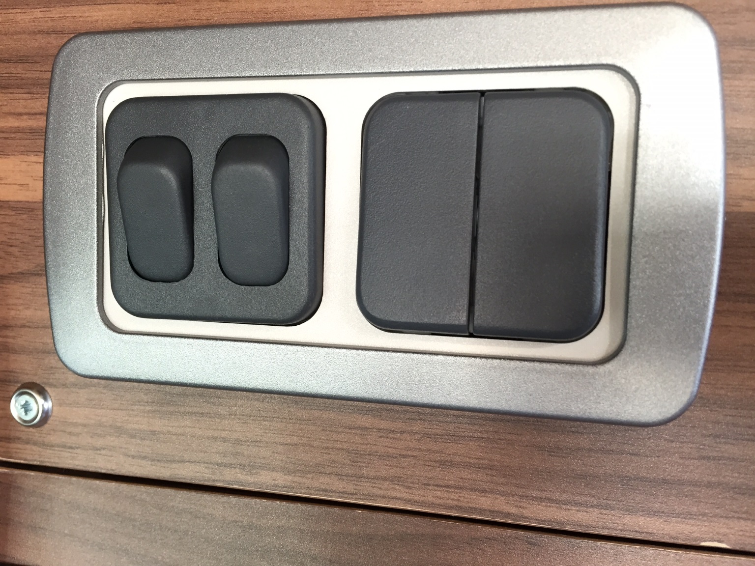
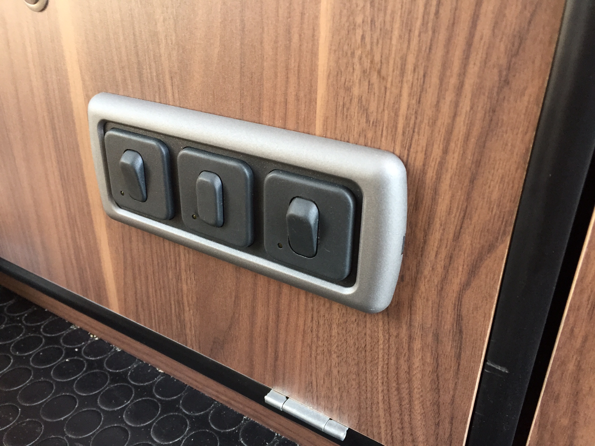
All the light switches are installed in the "wiring closet" above and behind the driver's seat. The light switch is the double switch on the right, which controls the down lights and ceiling lights separately. the switch on the righ is reserved for electronics to go in later, such as the Wi-Fi router, Apple TV, etc.
Inside the wiring closet is another nest of cables, although there is going to be a lot more as I add bits of electronics in there. I've run the cables to the front cover using a length of 20mm corrugated conduit and a pair of 20mm saddles.
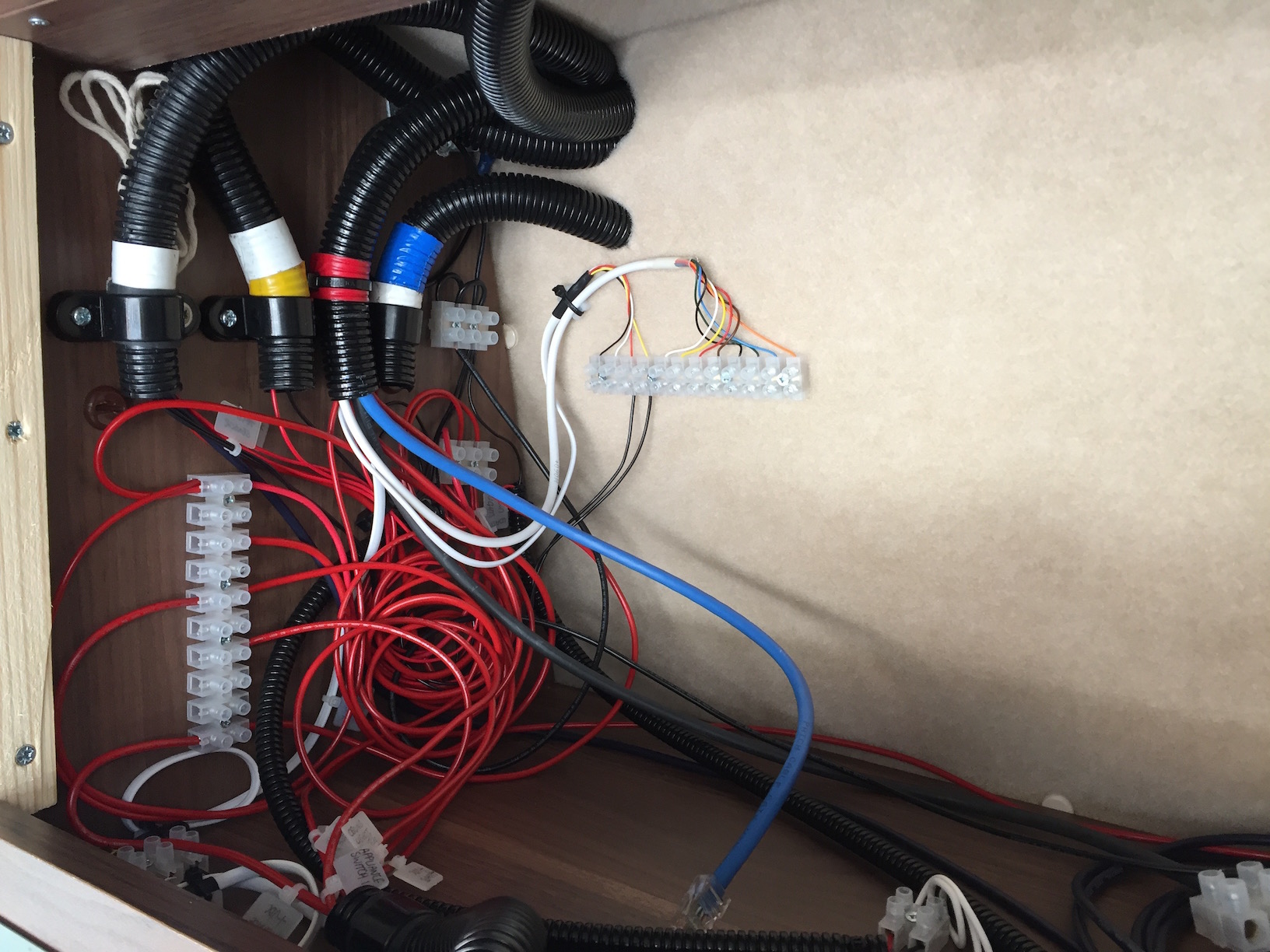
Later on, I am planning to cut the wiring closet cover panel cover in half (vertically) and replace the right hand side with a perforated stainless steel mesh for ventilation.
I also installed a 12V socket in the rear column, for powering mobile 12V appliances with bigger power requirements than the USB sockets allow. For example, a pump to fill the water tank or a compressor to inflate the tyres.
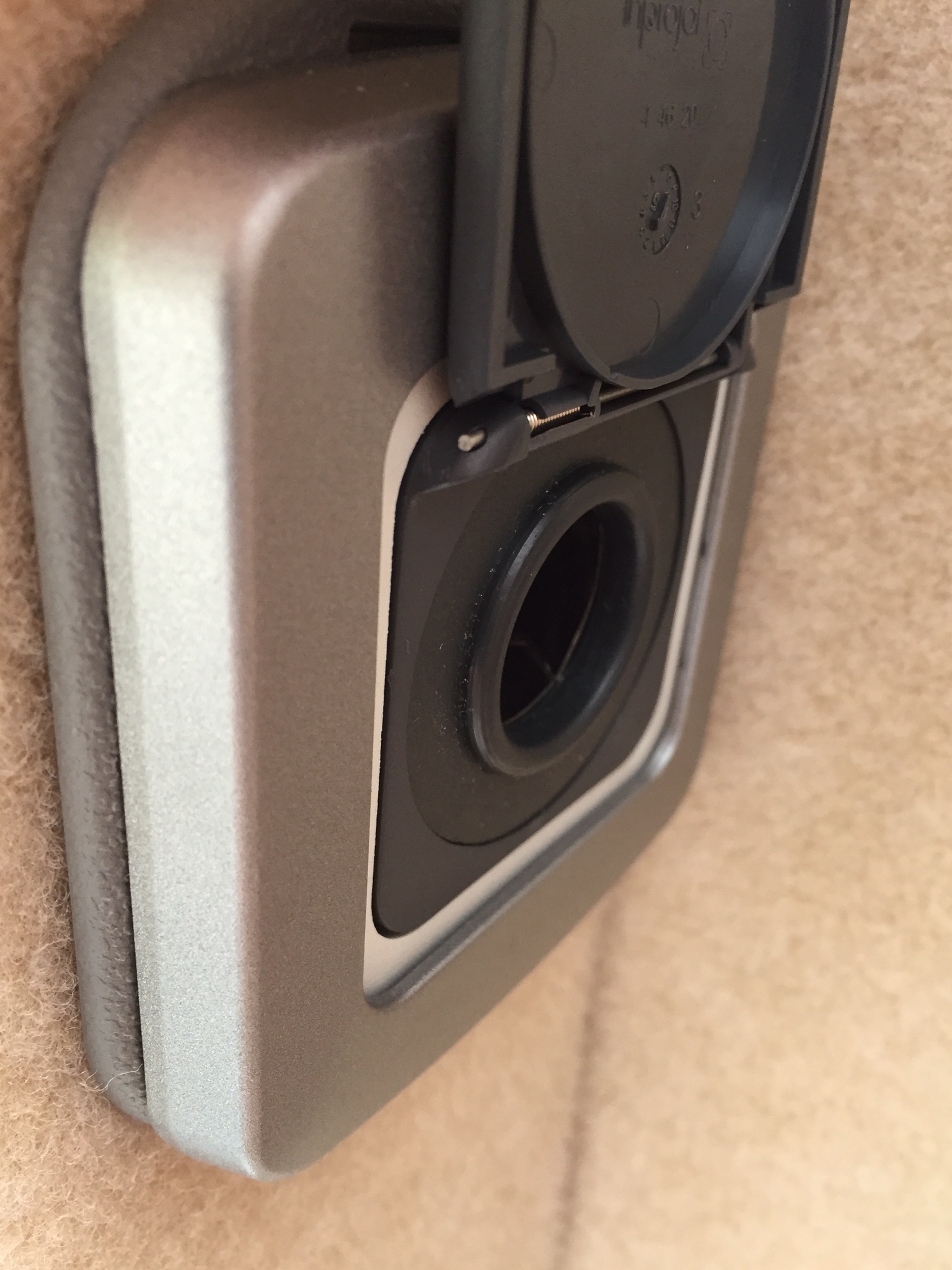
I bought a pair of these CBE sockets from eBay, however they were £20 each, which I thought was ridiculous. I think I only really bought them for the bright blue LED. If you can forgo the LED, get these instead from Bimble Solar and fit into a cheap CBE blank, cutting an appropriately sized hole with a holesaw before hand.
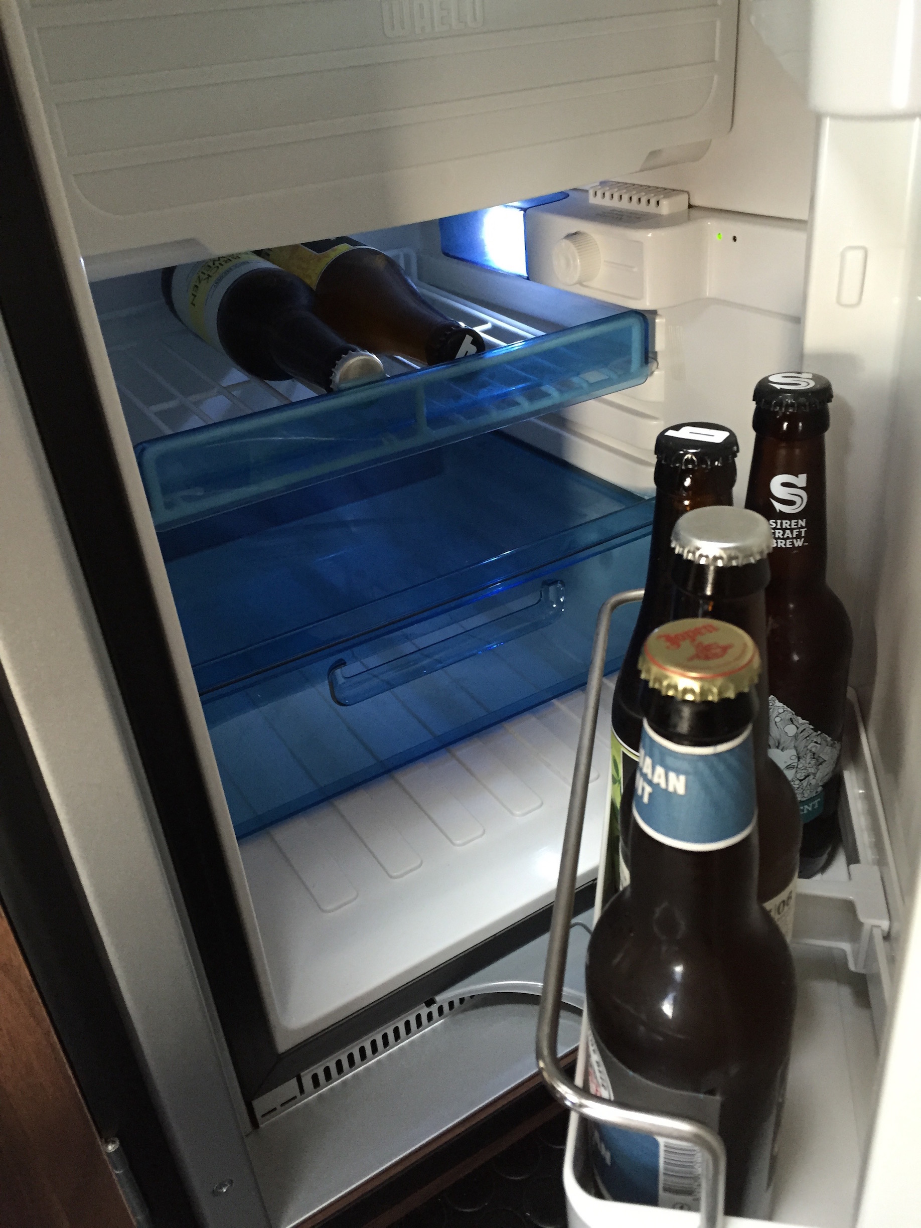
And most importantly, a cold fridge means one thing - cold beer! (ideally more than one)
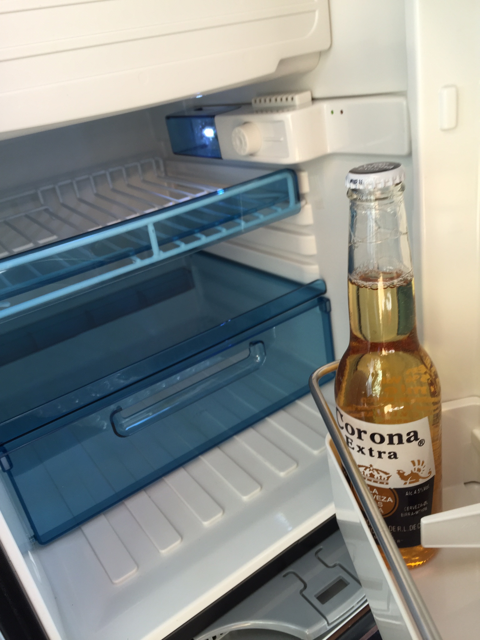
This is marginally better..
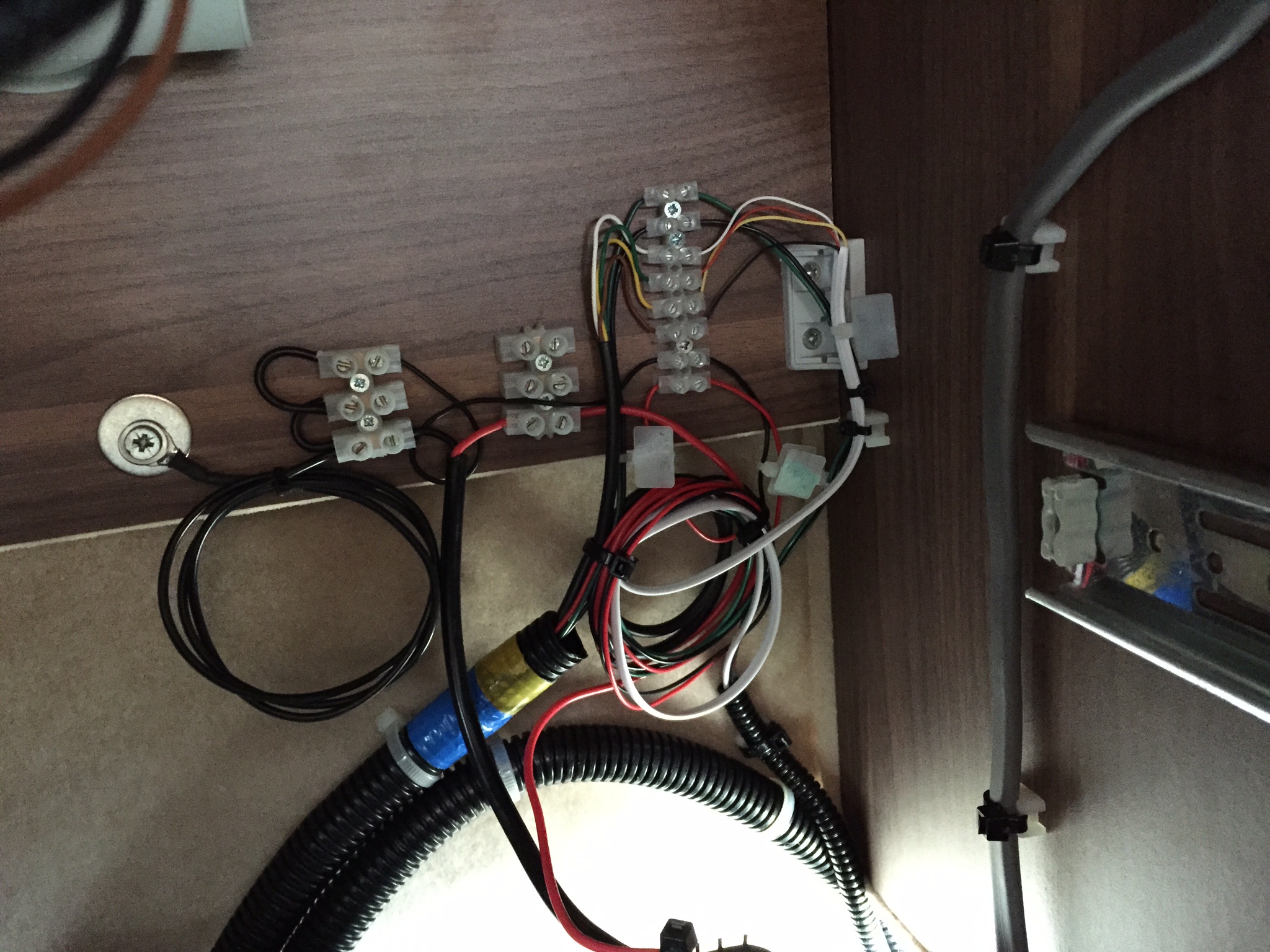
Connecting the appliances to the 12V supply was mainly by way of 20mm corrugated conduits running through holes in the cabinet work and terminated using connecting blocks of various sizes. Connections mainly terminate either above the fridge (behind the kitchen drawer) or under the boiler (utility closet).
I bought two types of conduits - one from Screwfix and one from 12 Volt Planet. The one from Screwfix is more rigid, smaller diameter and is very brittle. Use the one from 12 Volt Planet instead. Also, lay twice as much conduit that you think you may need, since it makes pulling looms of cable much easier, if split between two conduits, rather than forced through one.
The utility closet is all wired up now, with not much room left in there.

I've installed three CBE switches with LEDs for pump and tank defrosters on the door, using some corrugated conduits and two 20mm bar saddles to keep the wires from snagging when opening and closing the door.
And behind the fridge, a nest of cables with a ground point taken from the chassis via on of the kitchen cabinet fixing screws..
230V AC Electrics
Schematically, the 230VAC system looks like this.
Mains Hook-up
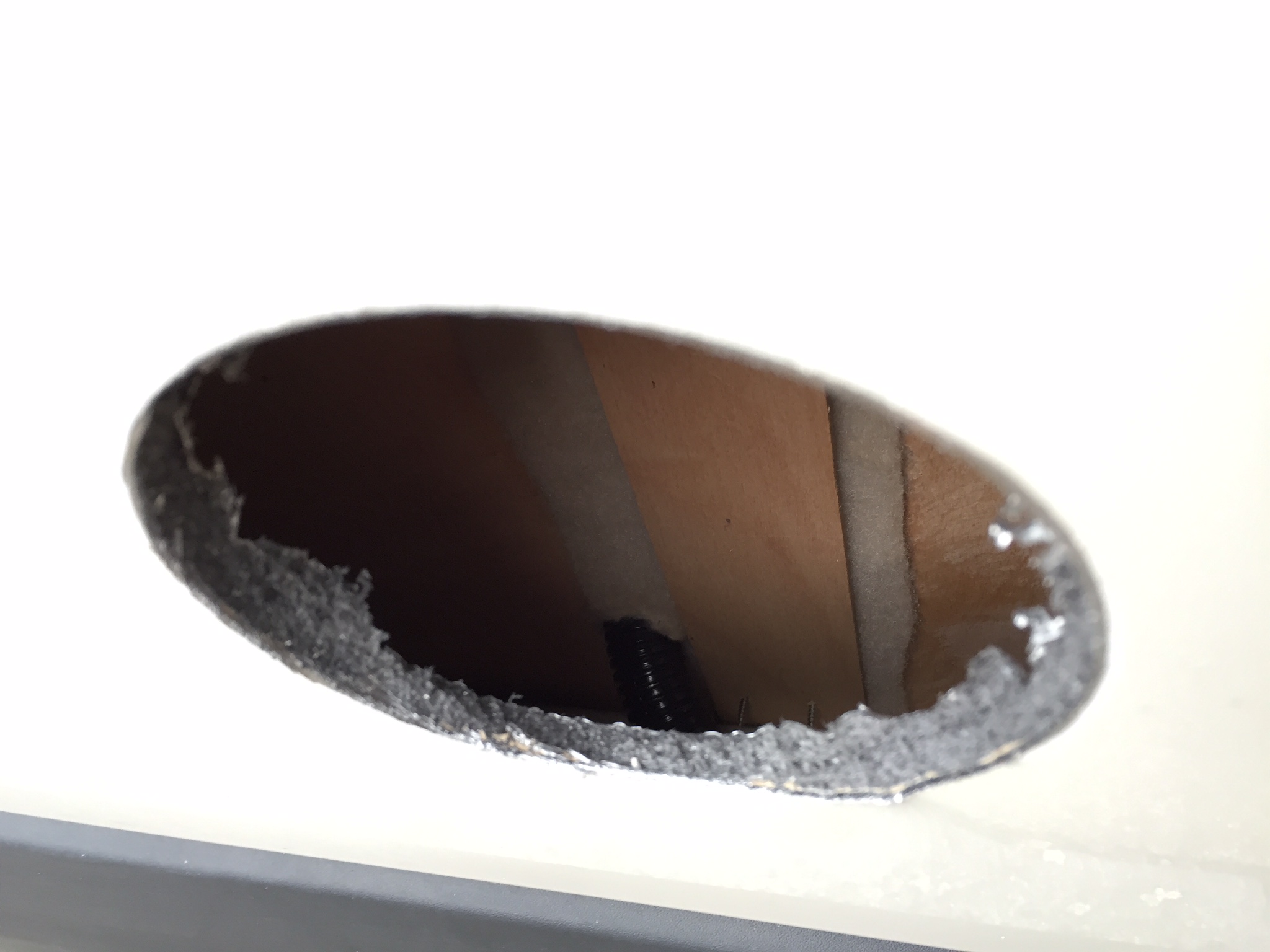
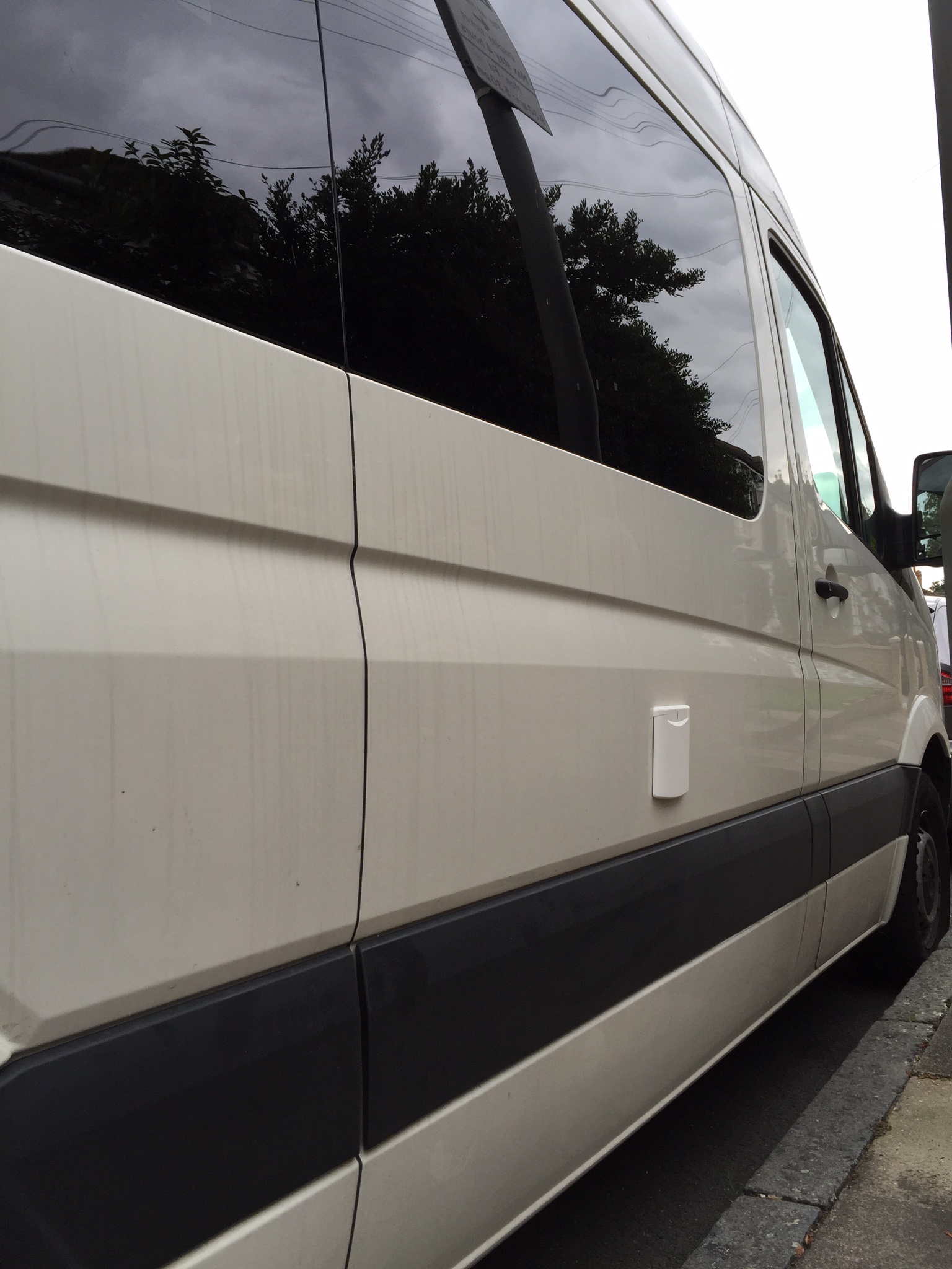
First things first, I needed to make another hold in the van for the electric hook-up socket. This time, a bigger diameter hole, for which I had to buy a new 92mm holesaw bit.
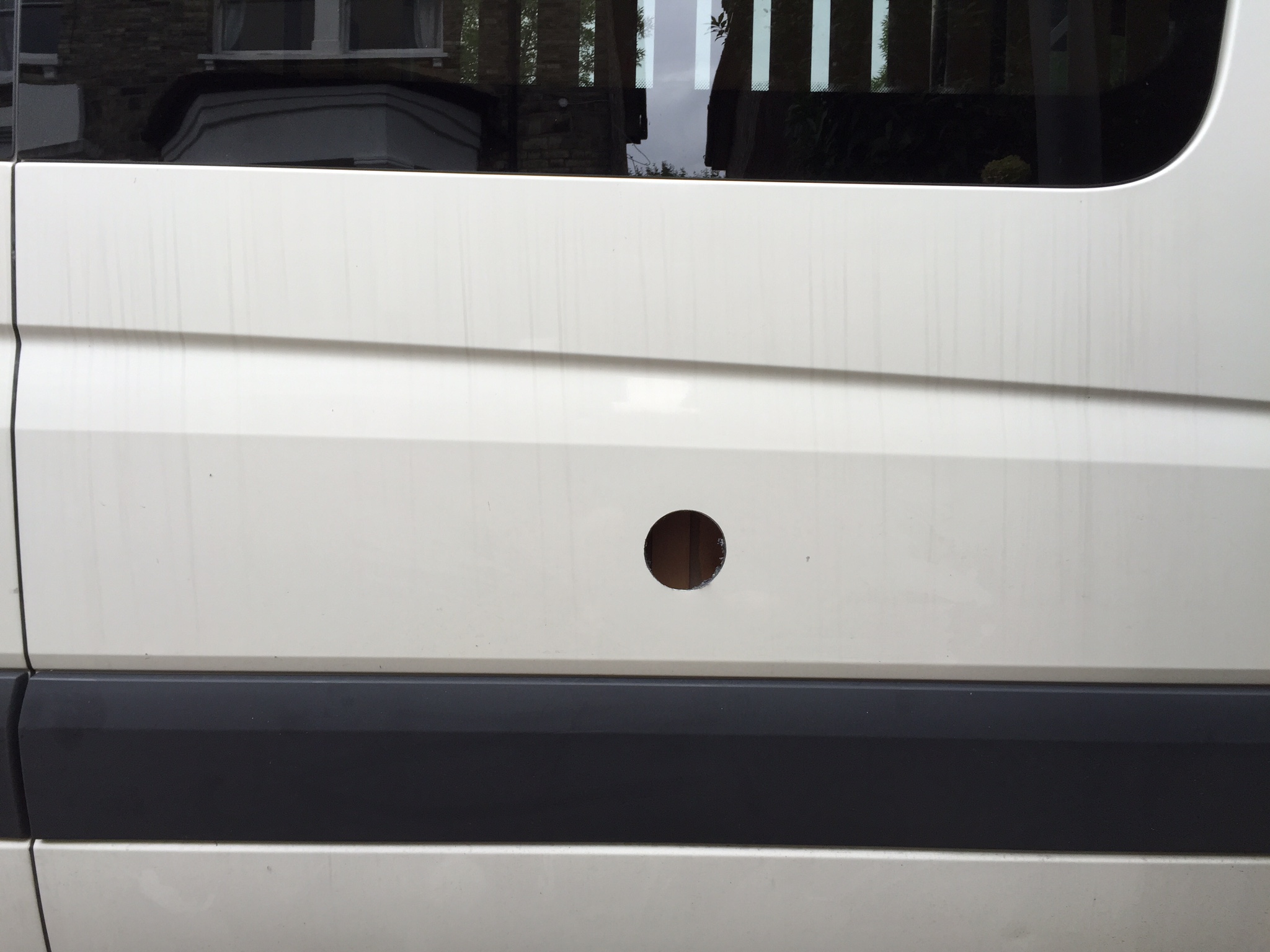
Into the fresh hole, I installed a Mains Elegant socket, which I purchased from Rainbow Conversions
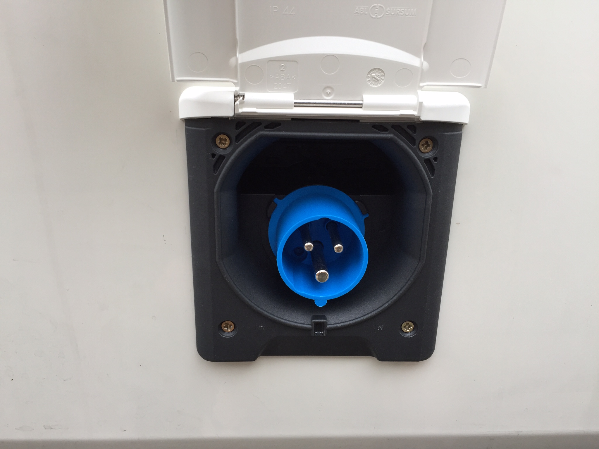
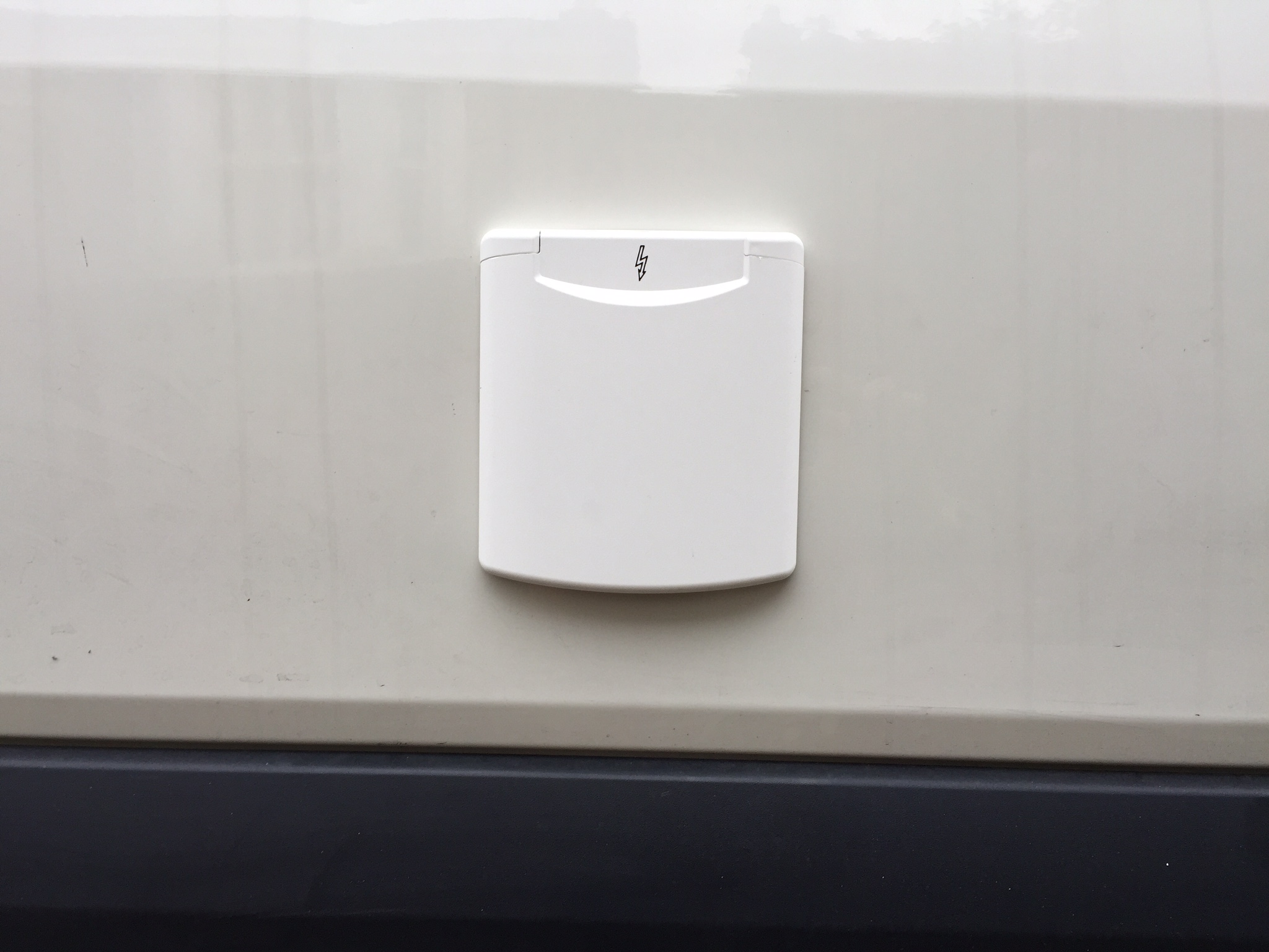
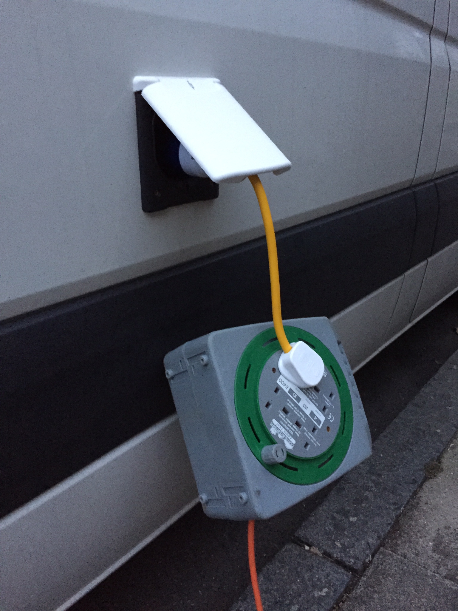
Having wired up the socket - a quick test to make sure everything was wired correctly..
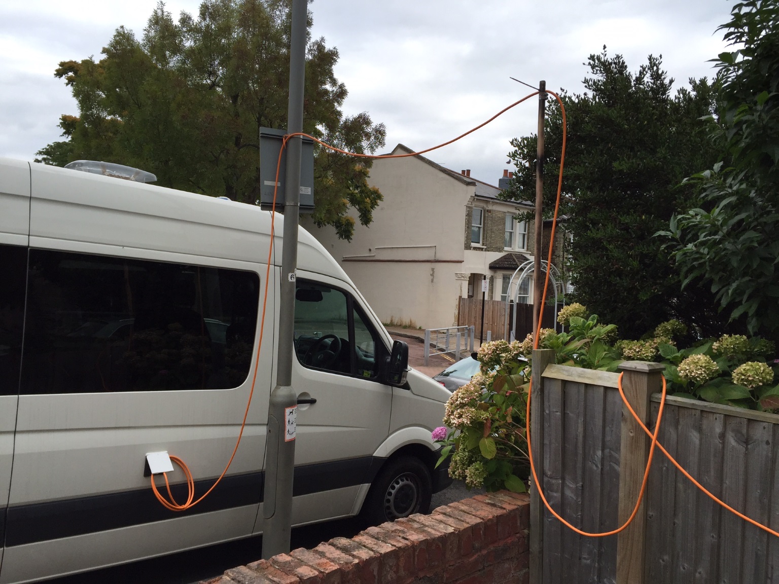
Afterwards, with some further modifications to an old curtain rail, I've put in a more permanent solution, at least until the conversion is complete.
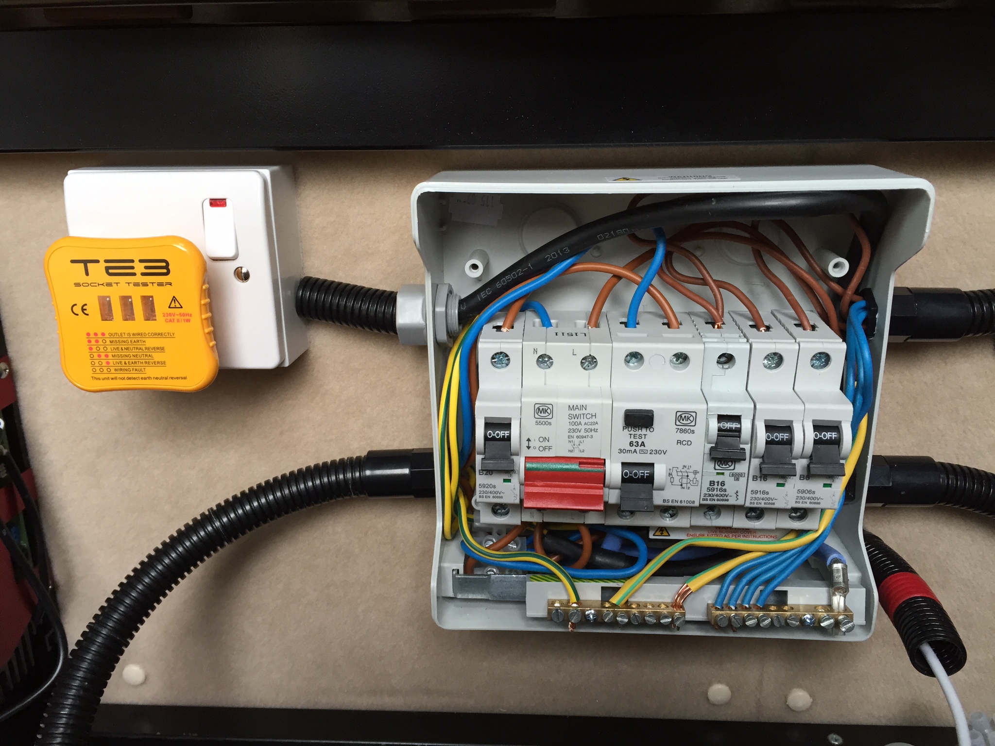
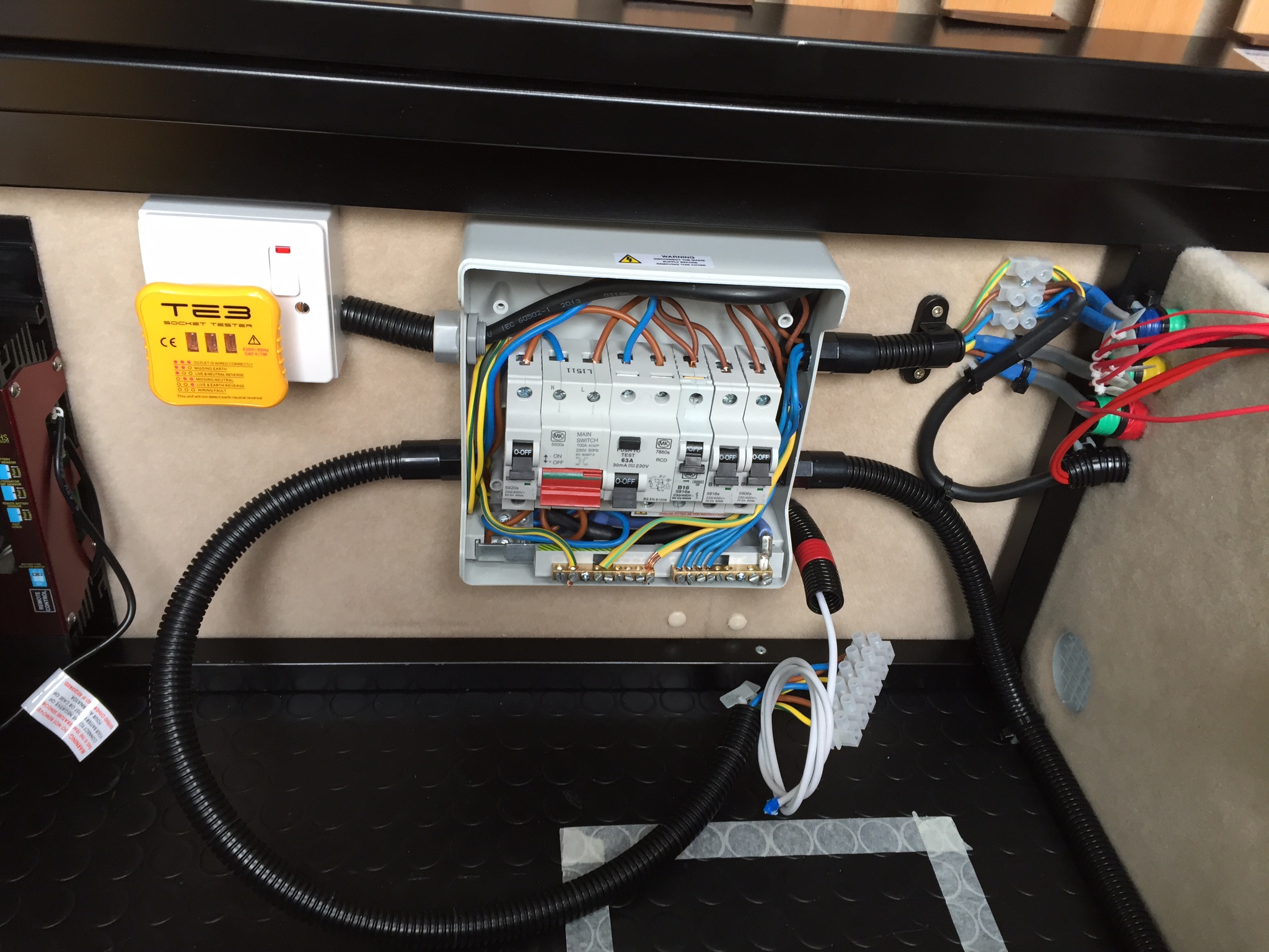
Consumer Unit
The consumer unit houses the following components (from left to right)
- Input AC breaker (20A) to charger
- Master ON/OFF switch
- RCD (63A)
- 16A MCB for boiler hot water circuit
- 16A MCB for 230V sockets circuit
- 6A MCB for the shaver socket
There is probably no real need for a shaver socket, however I bought one years ago and could never use it because of the wiring limitations in our bathroom. So this was the last chance to put it to work and so I did..
I've used 4mm2 flexible cable all the way from the mains socket to the consumer unit, then to the AC IN on the charger/inverter, and finally back to the consumer unit's via charger's AC OUT into the RCD.
Afterwards, I've used a mixture of 1.5mm2 flat solid-core cable and solid-core round (outdoor) cable. Some people will tell you not to use solid-core cables in motorhomes and boats due to the excess vibration generated by moving/engine. There is probably an element of truth here, however I've had all this left over copper cable from wiring up the flat and I wasn't going to go and buy any more flexible cable, so instead, I've secured each with saddles/zip-ties. If they ever come undone, I will be very surprised. In any case, there is always the RCD..
If you are interested, here is the only resource I used for consumer unit wiring..
I'v run a 1.5mm2 cable to a test socket with neon ON/OFF switch, directly from the main hook-up input. That way we can test for reversed polarity, missing earth, etc., before flipping the master switch or if the entire electrical system inside the van fails, we can still get a supply internally directly from this socket.
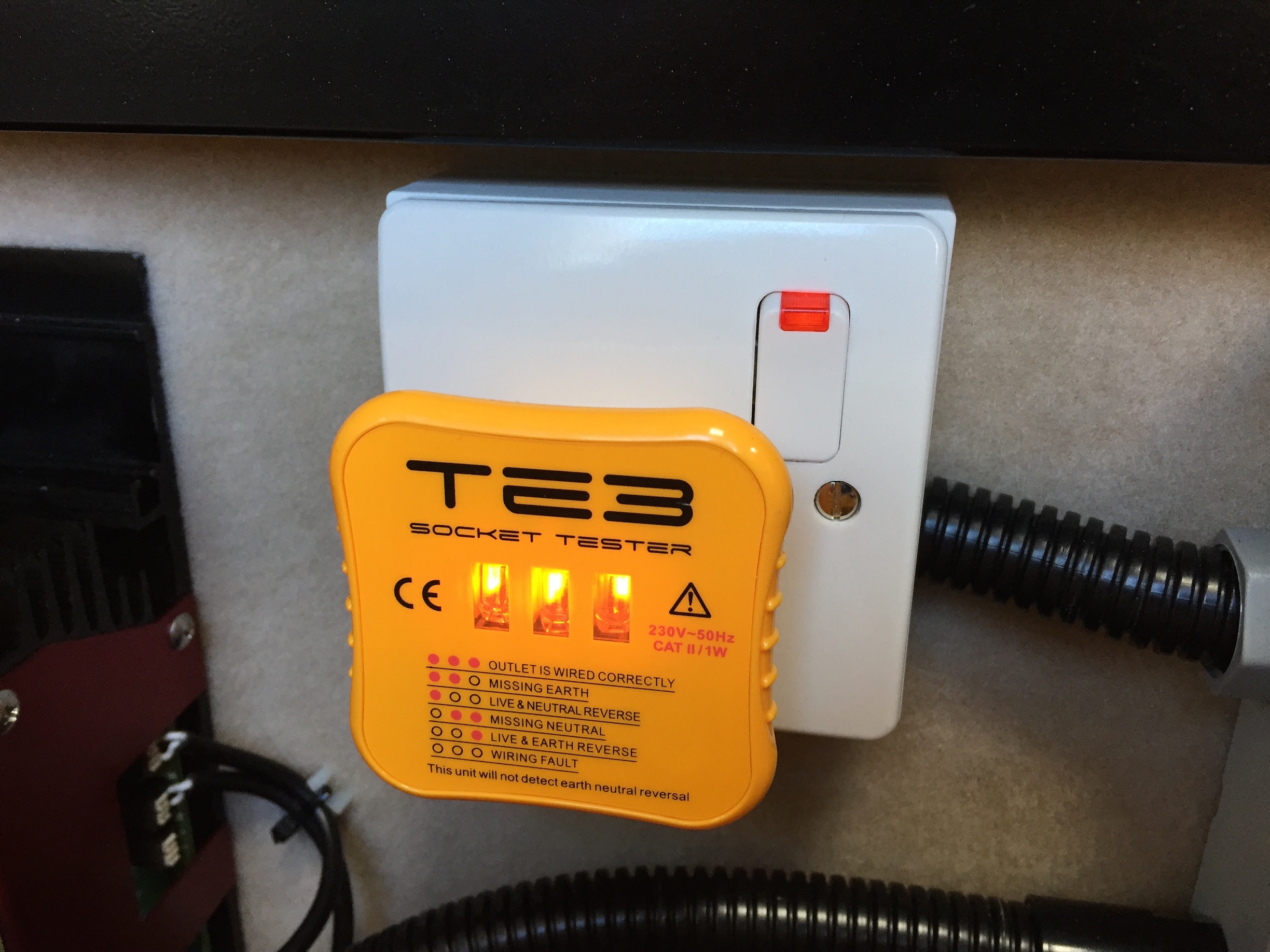
This is what our consumer unit looks like when wired up.
Sockets
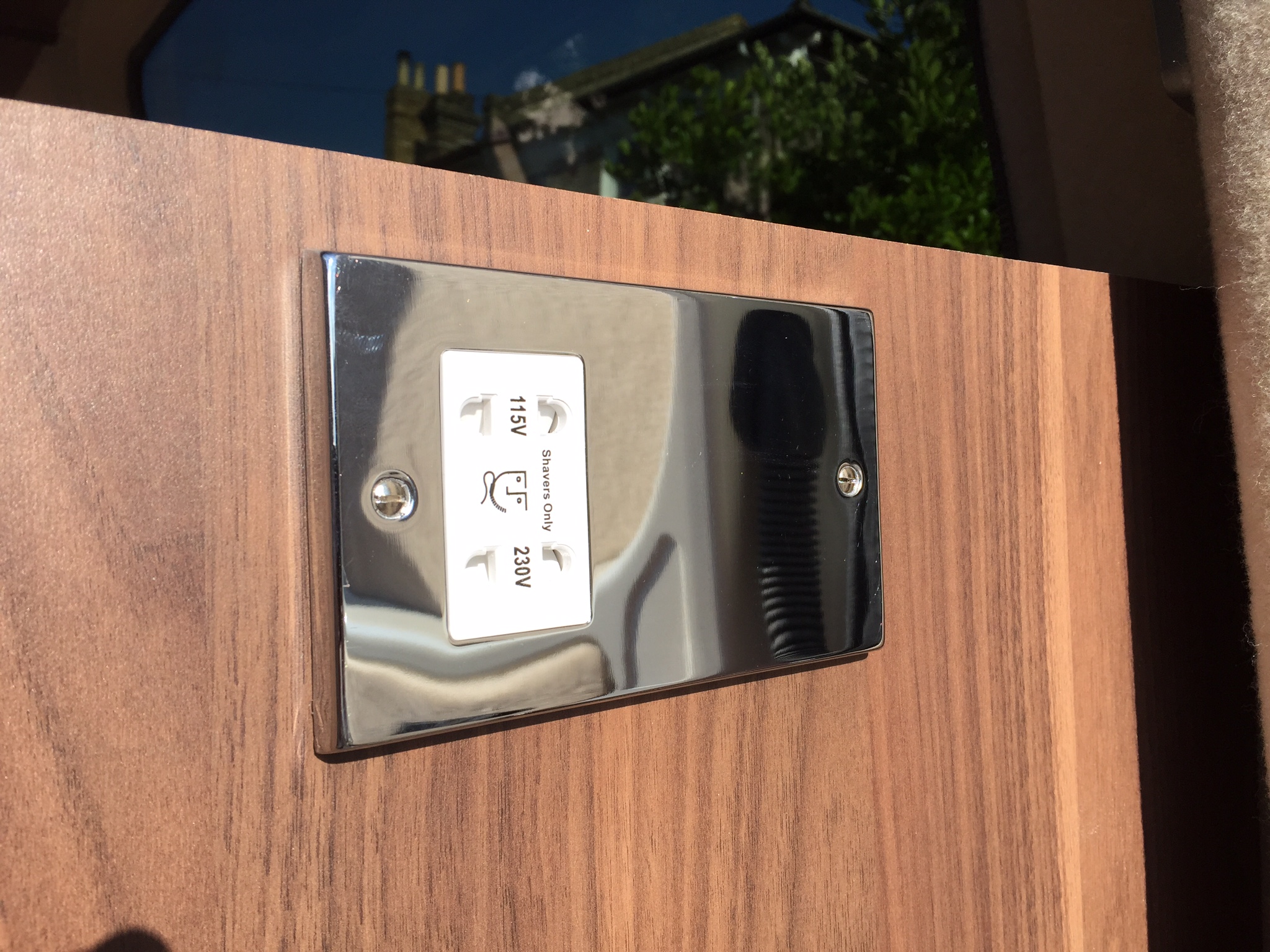
I've put the spare shaver socket on the side of the kitchen cabinet, with the view of charging electric toothbrushes and shavers.
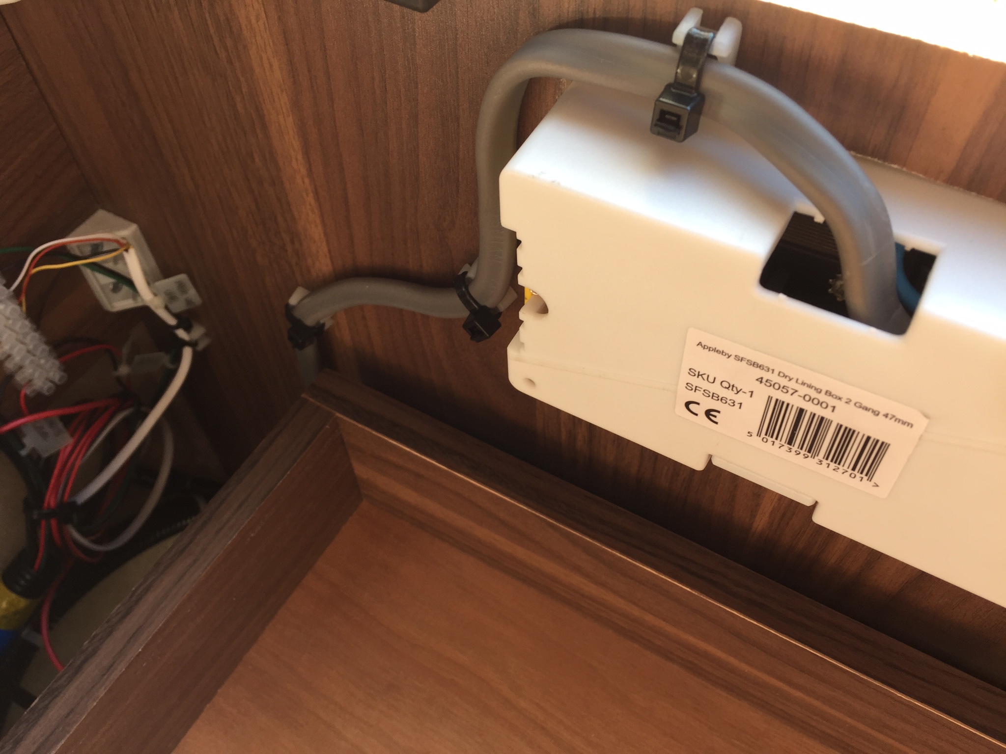
For appliance sockets, I've put in 2-gang socket with USB ports in the bed base.
This is the second time I had to install this socket. The first time, there was an oversight with the positioning. Ooops..
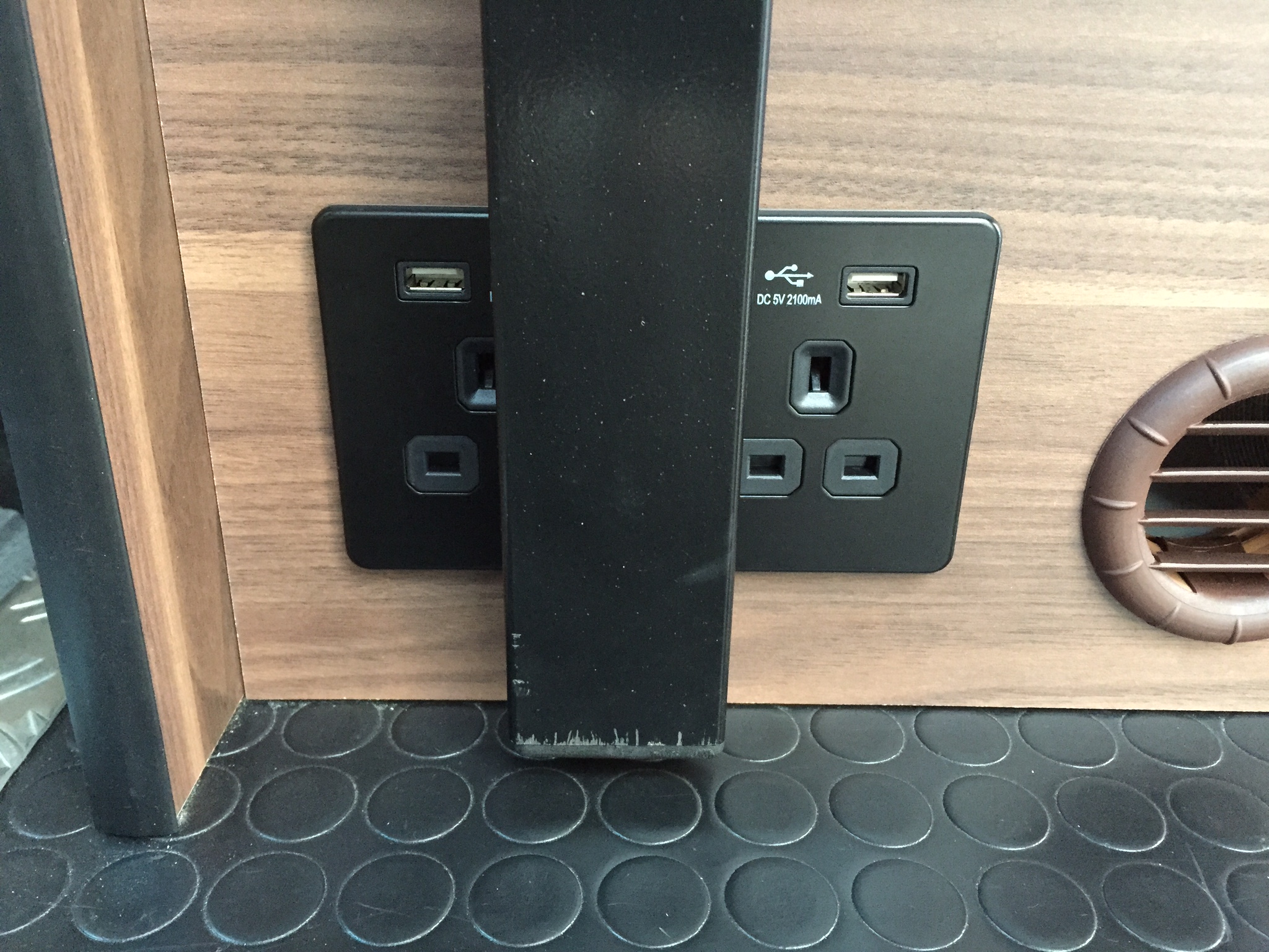
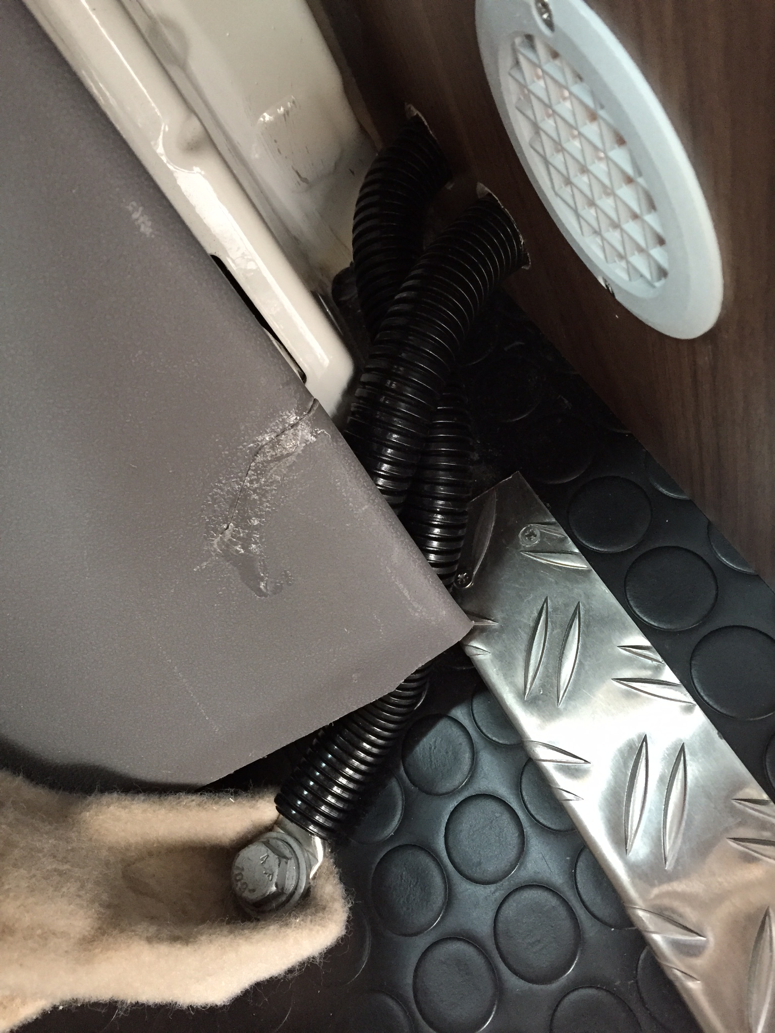
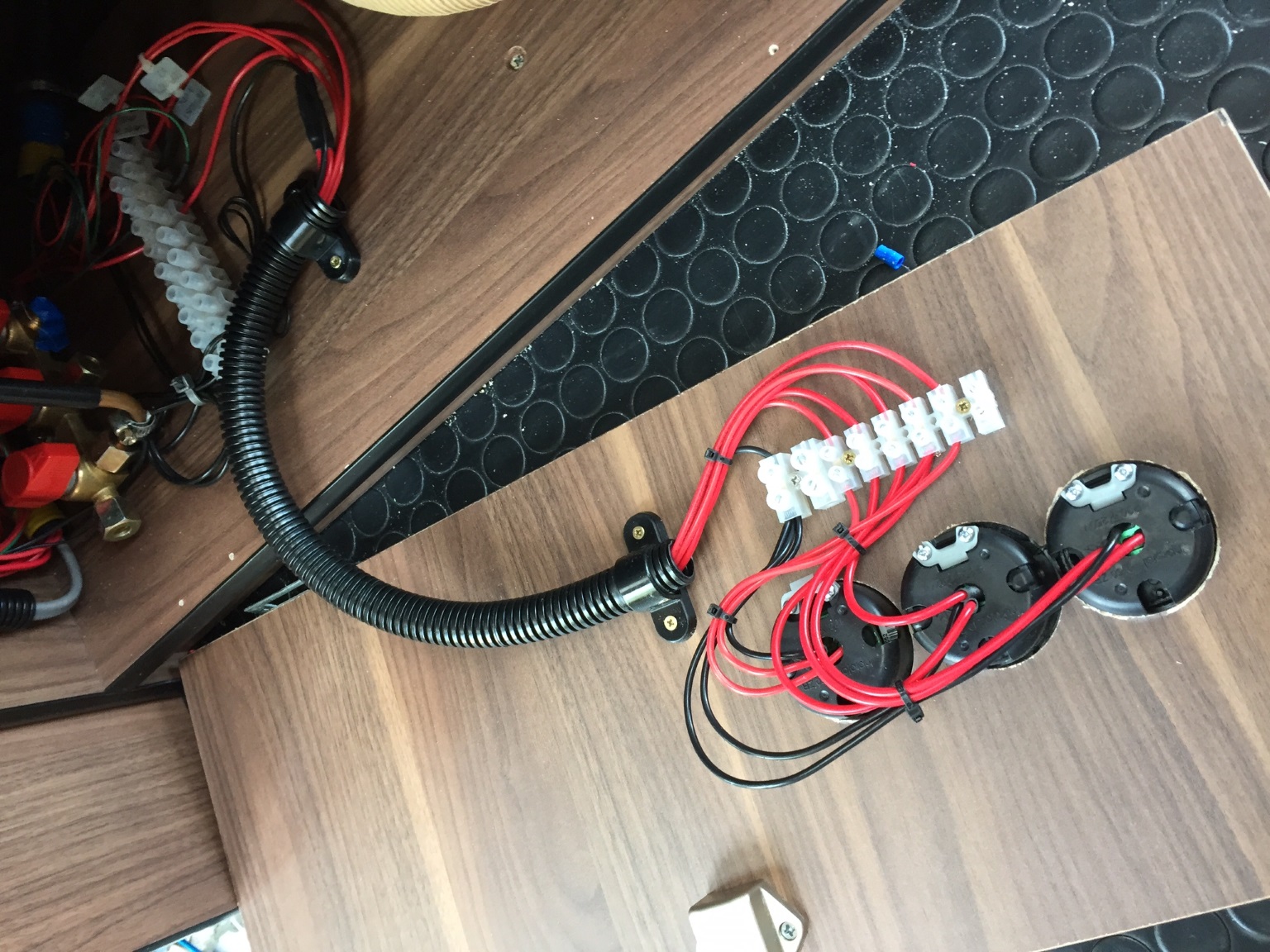
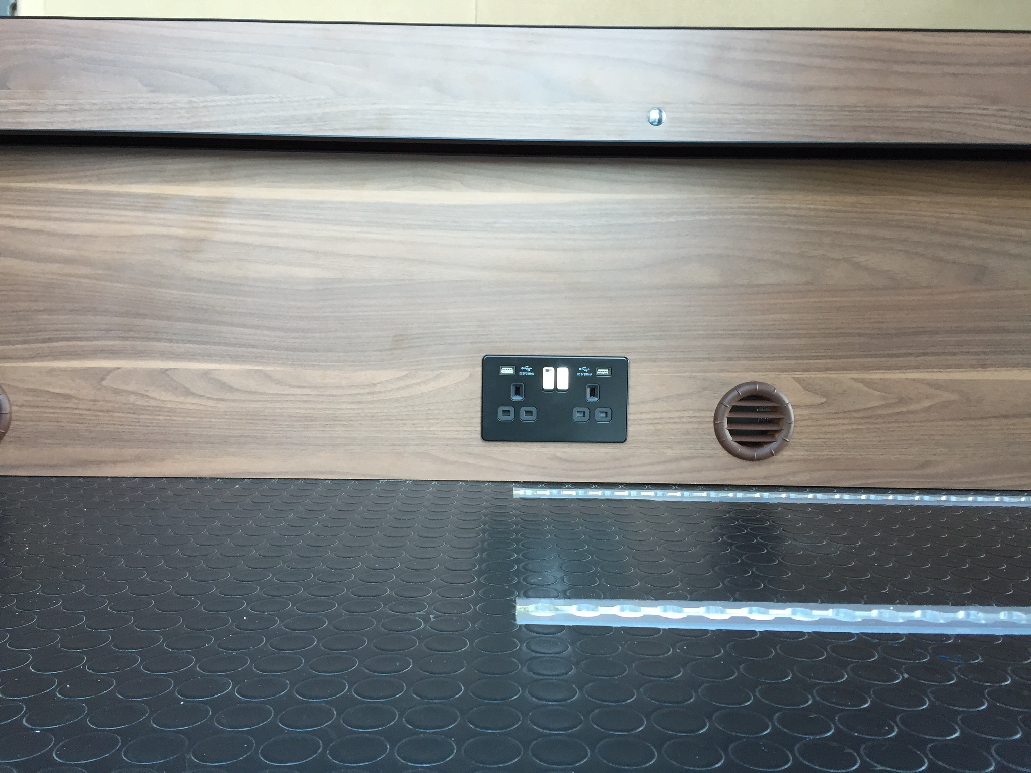
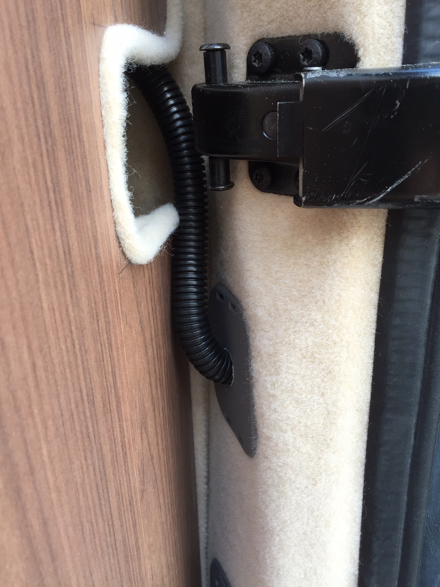
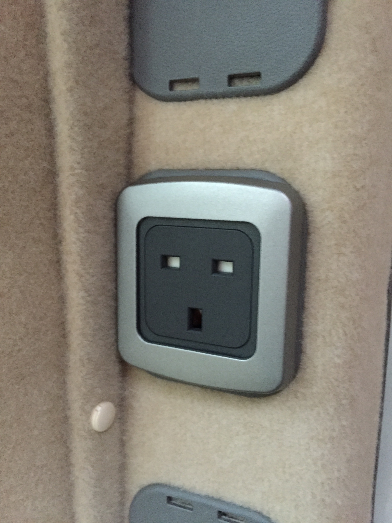
For the remaining sockets, I've decided to make use of the three ports in the rear pillars, given they already have a number of manufacturer cable looms running through there. It seems to be the obvious choice. You can see then in the right corner of the following image. There are five of them all up, so I've used the top three for sockets and the bottom one for the supply cables. The one up from the bottom has a grille for ventilation. This is the same for both sides of the van.
The supply cables were fed into the pillar through a 20mm hole in the covers and inside a 20mm corrugated conduit. I've since had to cut an additional 10mm hole to feed through an additional 10mm convoluted sleeve with additional cables for water tank levels and USB/12VDC sockets.
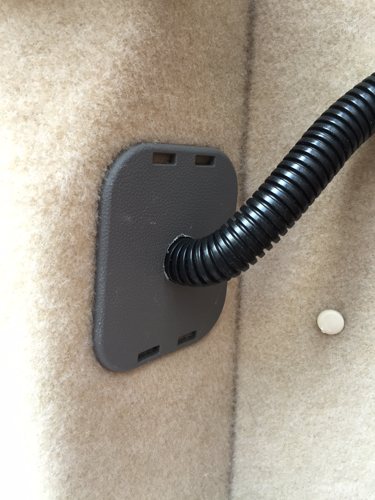
The CBE sockets were fixed to the blanks in the following way. I made a 32mm hole with a holesaw in the centre of each blank and fed through the wire into the CBE back-box.
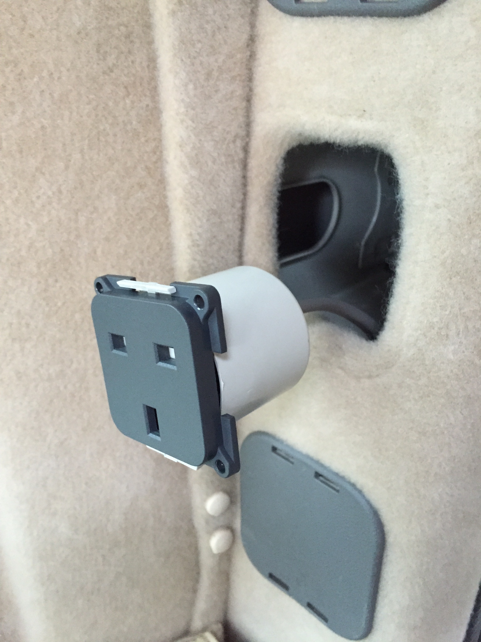
I've then fixed the socket to the blank using a couple of wood screws.

Then, I've fixed the frame to the blank with another couple of screws.
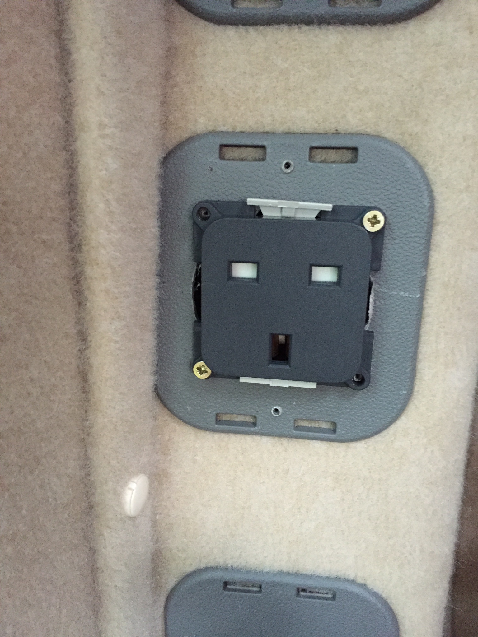
And finally attached the flat-line 1-gang CBE plate.
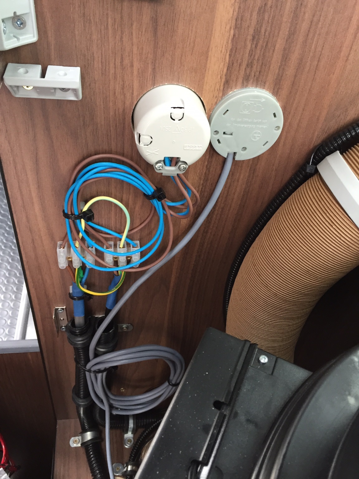
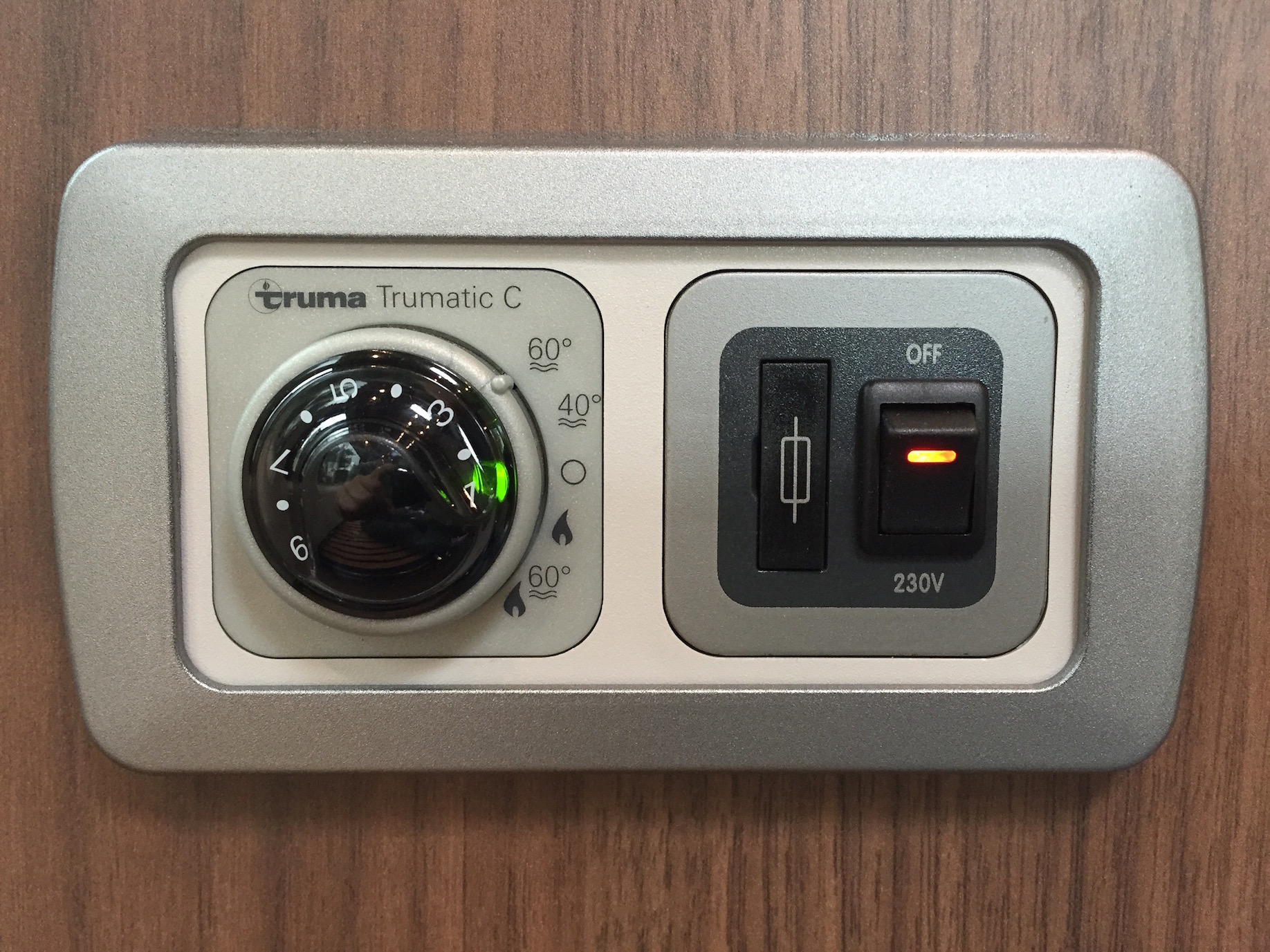
Boiler Hot Water
Our Truma 6002E boiler contains a separate 230VAC heating element for heating hot water only. The rest of it runs on LPG and 12VDC. Connection to the mains was made by way of a CBE fused spur (10A) in a double CBE flat-line frame, which also fits the boiler control switch.
So there you have it, the electrical system is done and seems to be working correctly so far. I have a new toy, a UNI-T UT204 Digital Clamp Meter on order, which I'll use to poke around to see how much current is being drawn on different circuits..
Coming up Next..
[Next]((http://anton.belodedenko.me/water-works/), water tanks, plumbing and a full heating/hot-water test..
Stay tuned as we are almost done..
