Soft Plastic (part two - The Extroodler) 🍜
In my previous post I built The Shredditor®™️ based on the Precious Plastic reference design, using, among other things, a donor treadmill for parts. In this post, I'll write about how I built The Extroodler to make 3d printer filament out of shredded plastic.
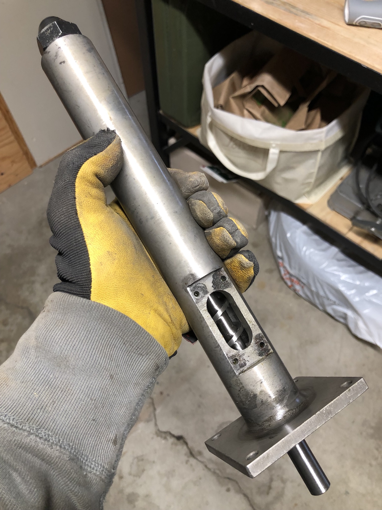
Precious Plastic (PP) also publish plans for an extruder, but for economic/availability reasons, I opted instead for a shorter and narrower (20mm vs 35mm) matched screw/barrel/nozzle from AliExpress.
Overall, I felt that building the extruder is mechanically simpler than the shredder, however, for a complete filament producing solution, there are a fair bit more components involved than just the extrusion machine. Broadly speaking, this is what I ended up with at the end:
- Extrusion machine (incl. frame, gearbox, motor/controller, filters, hopper, heating/sensors and electrical)
- Precision filament thickness roller gauge
- Filament puller and associated electronics
- Some sort of linear frame
All together, I am calling it The Extroodler®™️. 😬
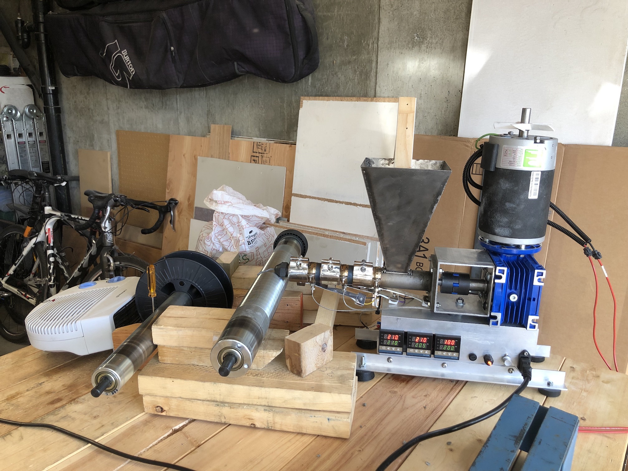
Extrusion Machine
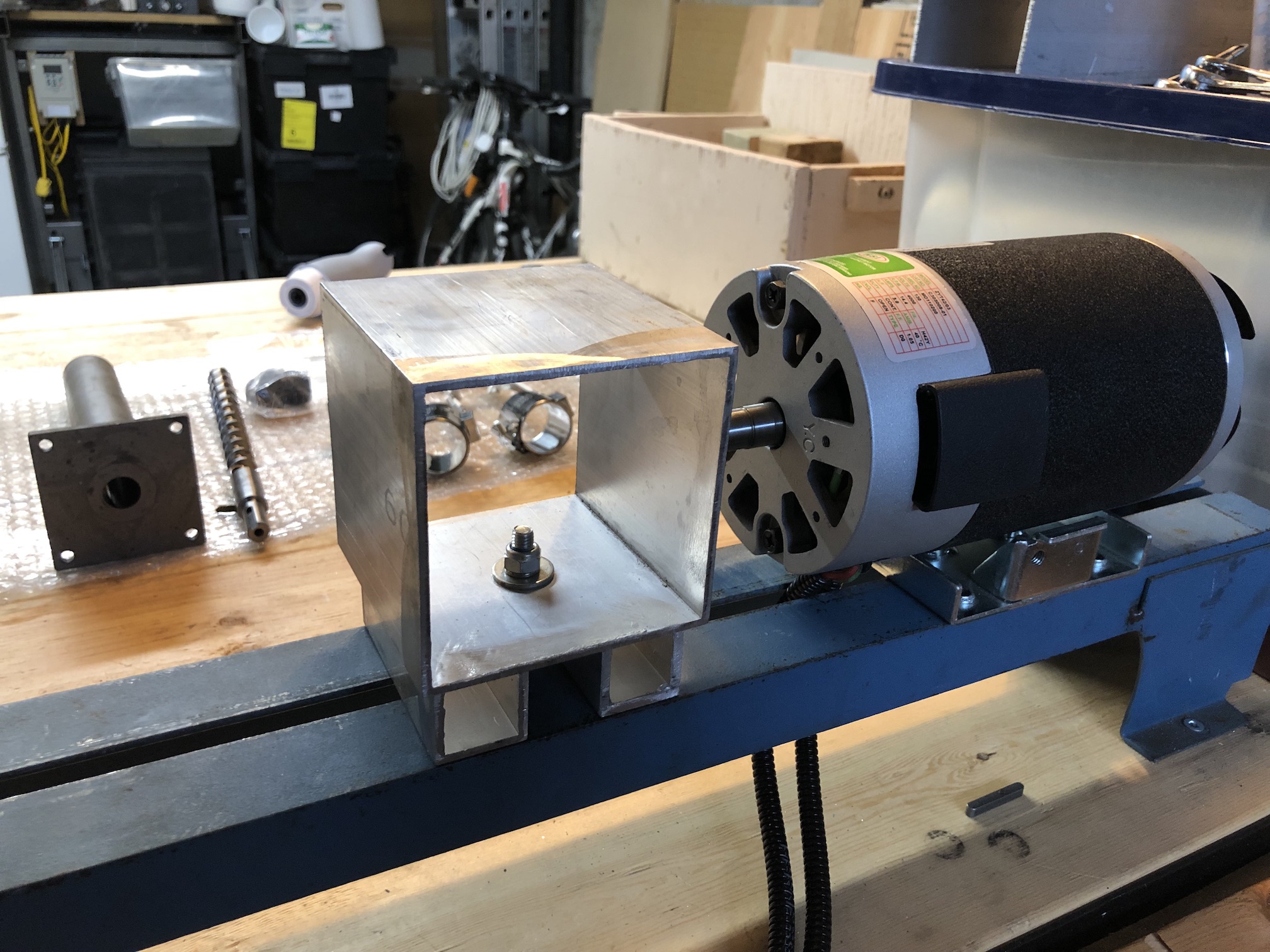
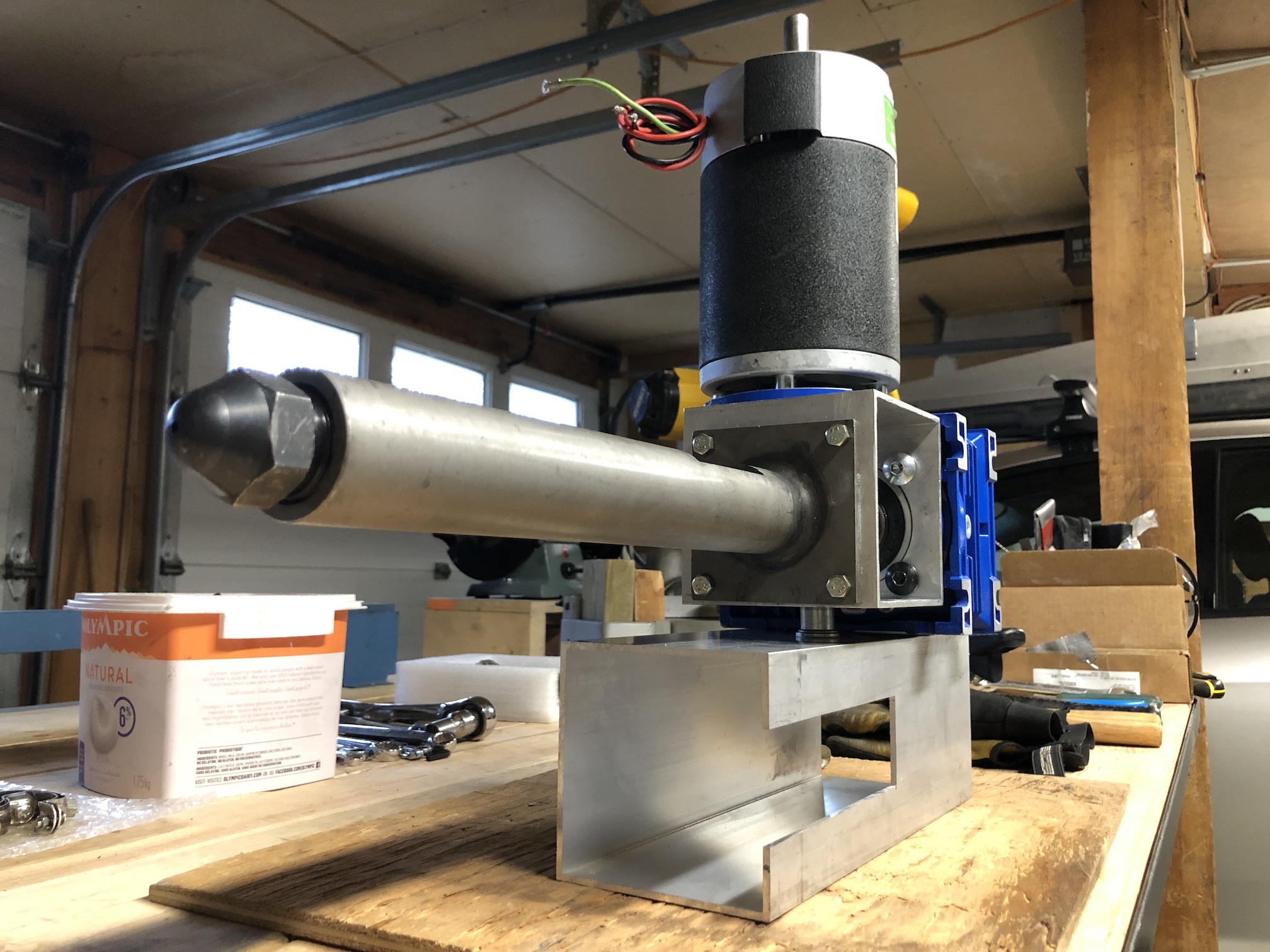
I try to optimize for reuse of materials, where possible and/or practical. To make the frame, I used a length of aluminium square tube 4x4" for the extrusion machine base and motor coupling.
For the hotend, there are a couple of vendors, which at the time of writing were carrying extruder barrel, screw and nozzle parts Robotdigg and JUGETEK. If you prefer to source the screw and barrel based on the PP design, you can check out the Bazar. You may be able to find the same on AliExpress also. In either case, going with AliExpress you can source most of the hotend parts in one place (relays, heating bands, thermocouples, etc.).
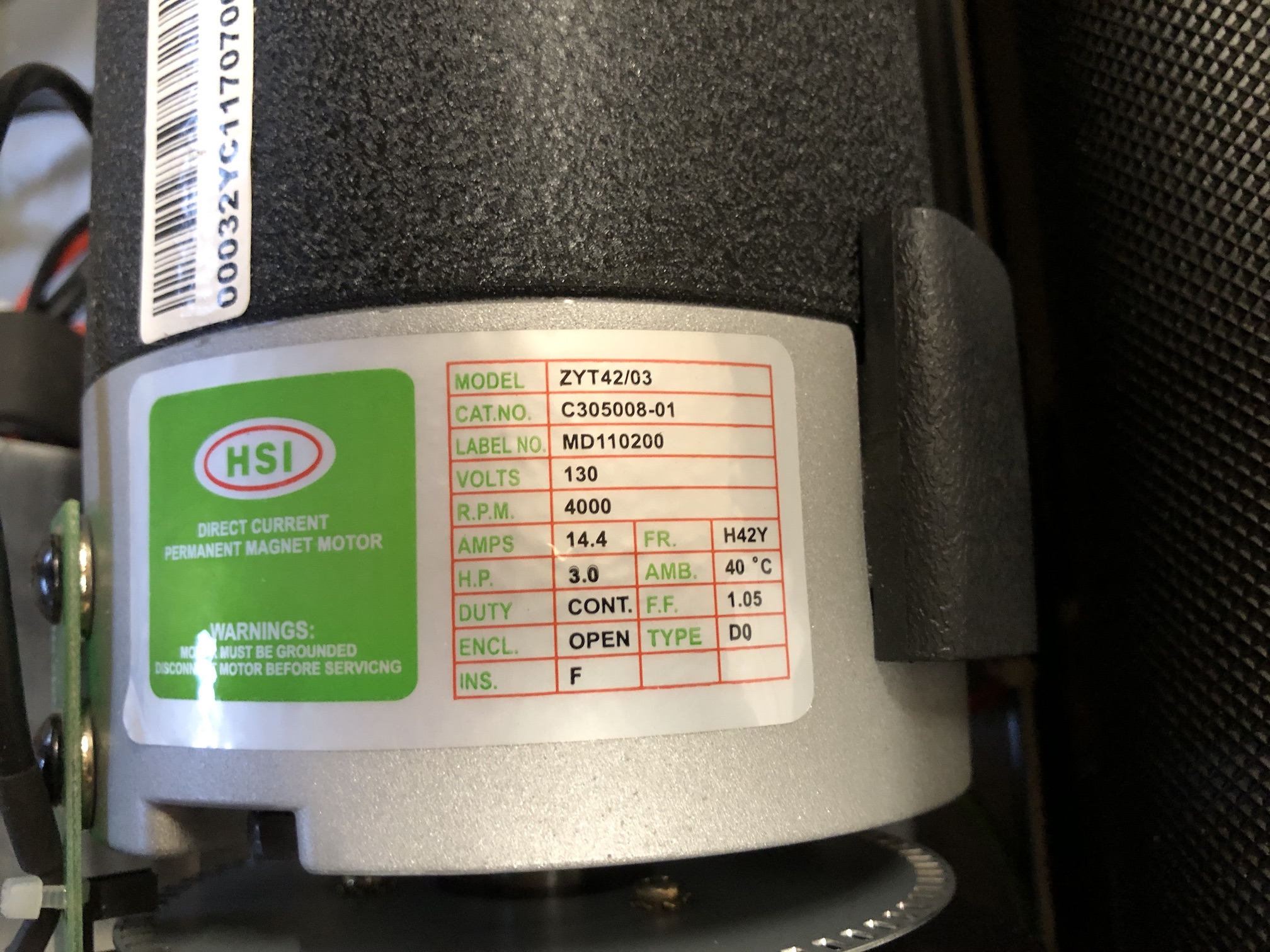
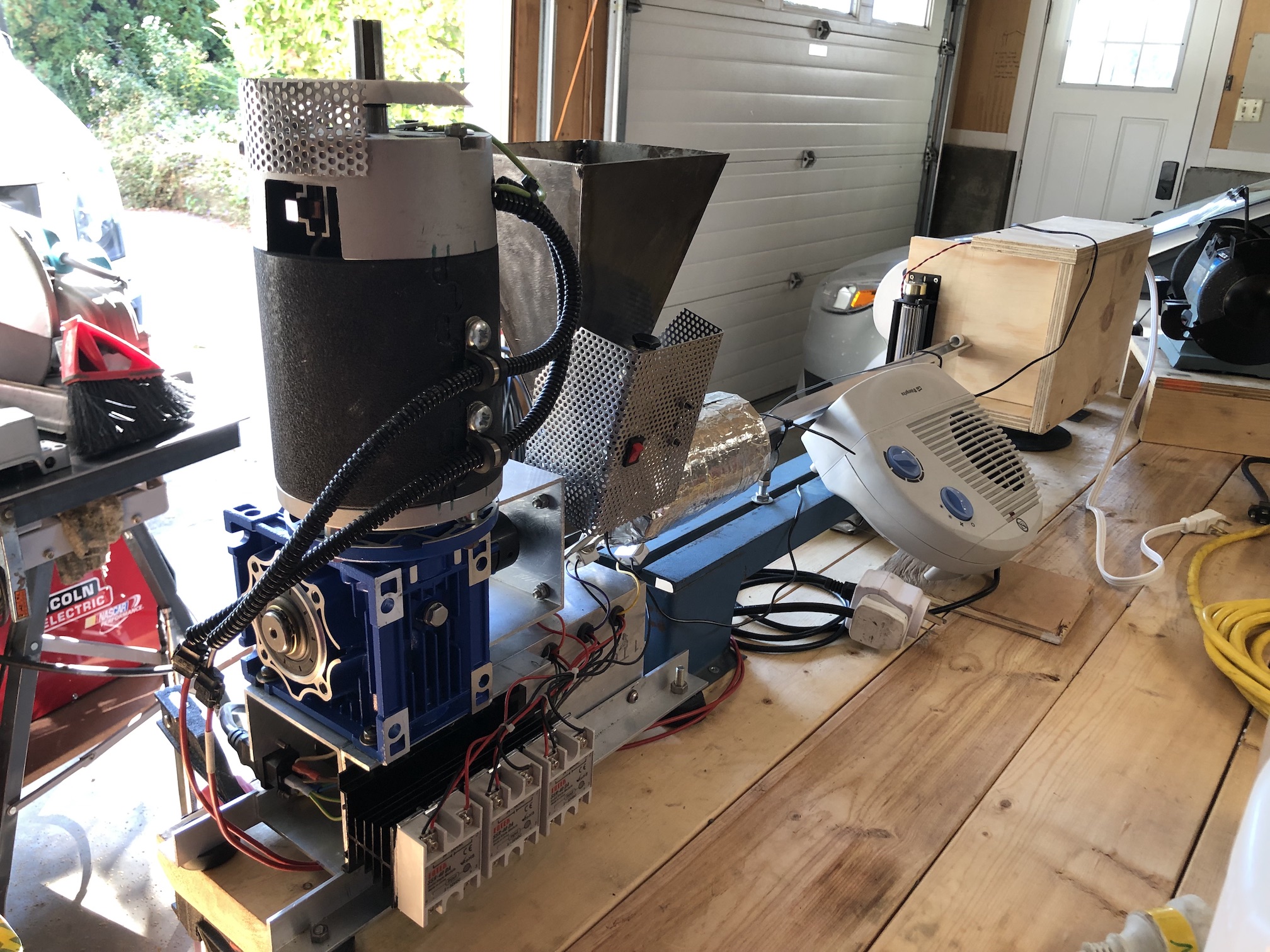
I had recovered a suitable DC motor from the treadmill a neighbour was throwing out because the logic board was faulty.
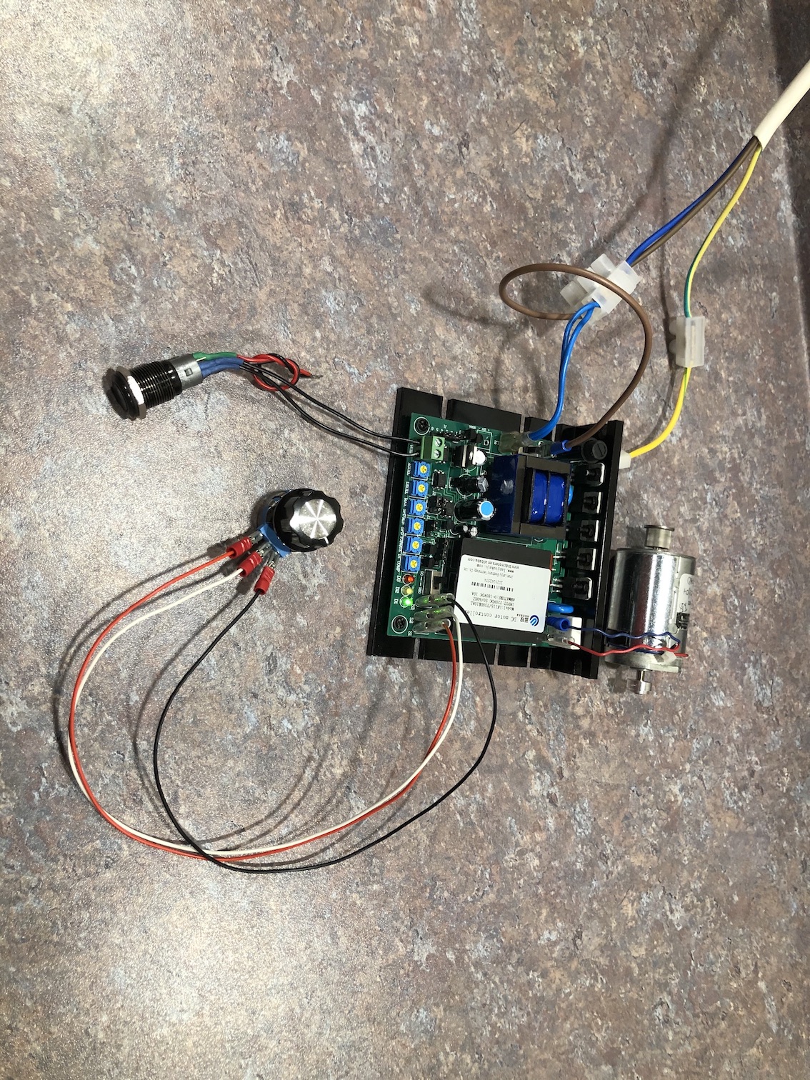
To drive the motor, I went with 115/230DR10AL-02 from Jinan Lanjiu.
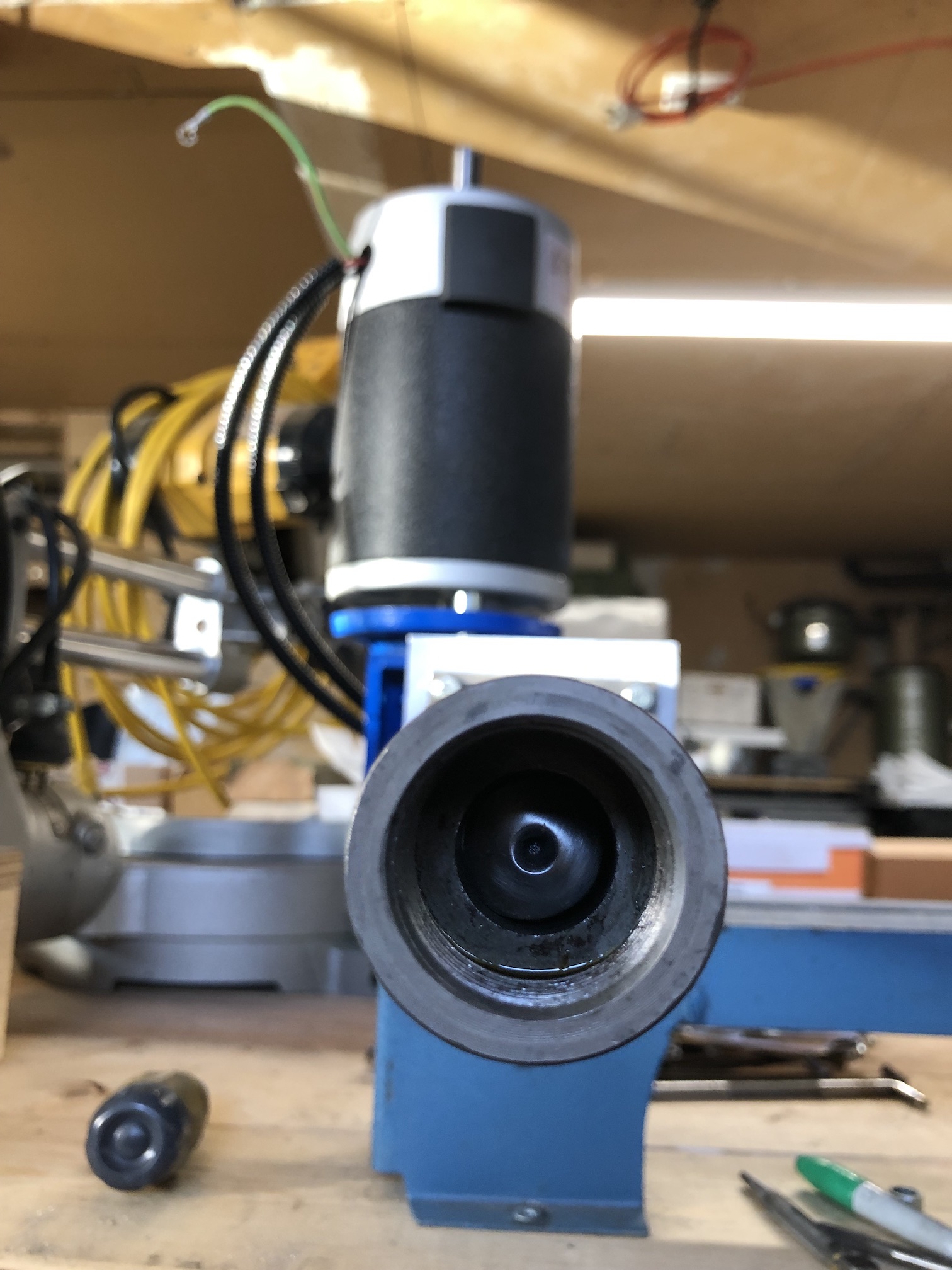
To reduce the speed and increase torque, I used a NMRV050 Worm Gear Reducer with 30:1 ratio and a 25mm single output shaft. I sourced this item new from AliExpress, but you may be able to get a deal on it second-hand from places like eBay, Craigslist or Facebook Marketplace.
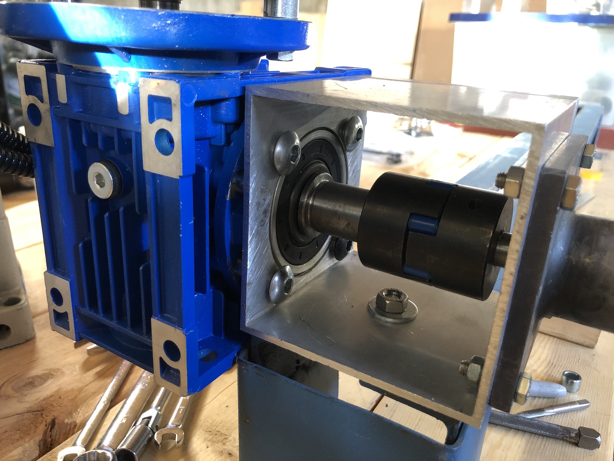
Appropriate jaw coupling, shaft keys and polyurethane spider can be sourced from AliExpress or you local machinist supply stores, like McMaster-Carr.
Coupling the barrel to the gearbox in my case was fairly straight forward. A very basic drill press was enough to cut/drill the holes. The motor coupling was a little more difficult, since the output shaft of the motor was 16mm and the gearbox input bore was 19mm. I used a length of aluminium pipe with a slit cut for the shaft key to make a collar/adapter and used a asymetric shaft keystock to make a slightly taller key. I then coupled the motor with the gearbox using spacers and lengths of stainless threaded rod, replacing the original four long bolts holding the motor together. I also had to print a new fan, since the treadmill original was designed for a different motor direction.
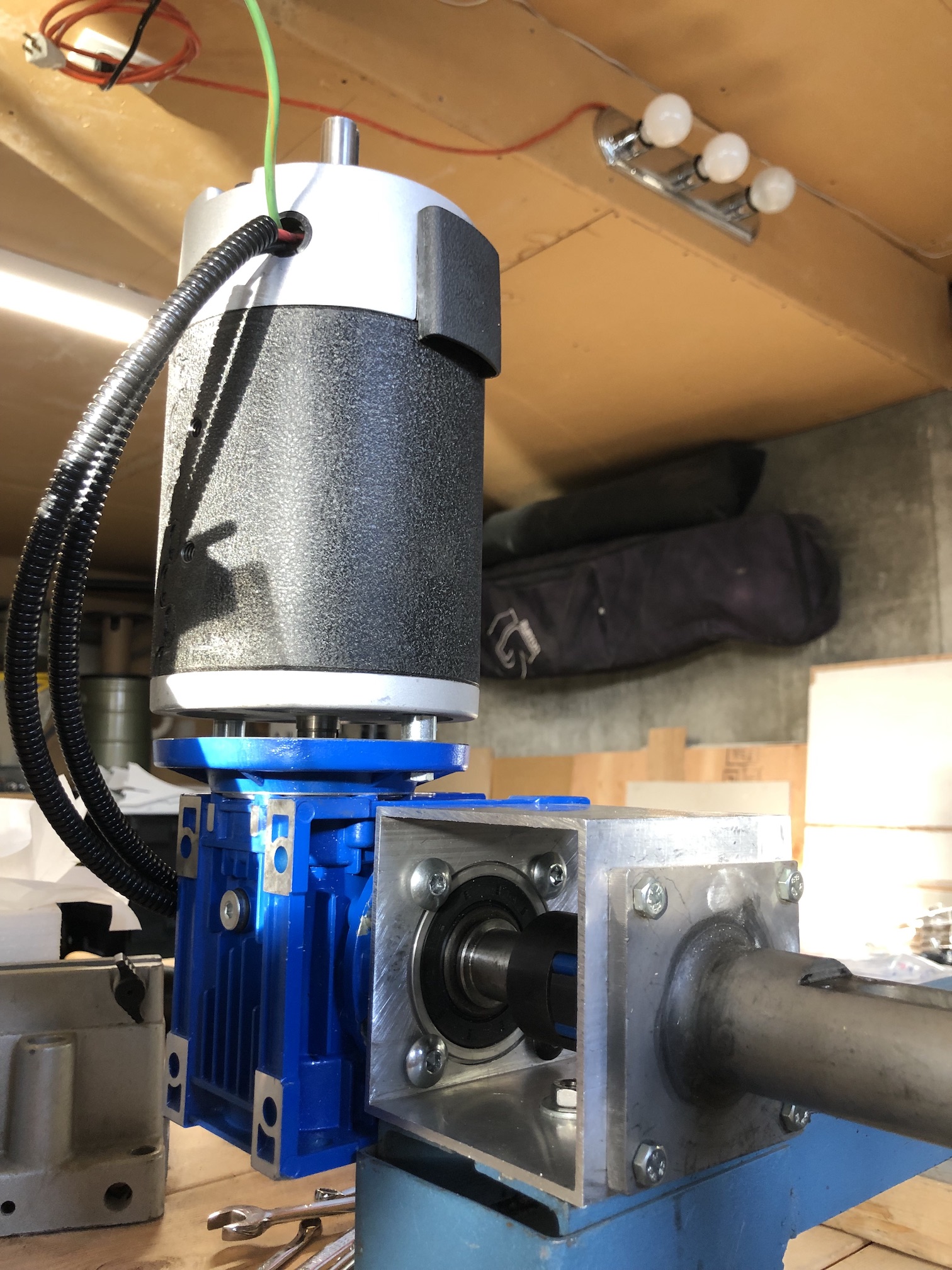
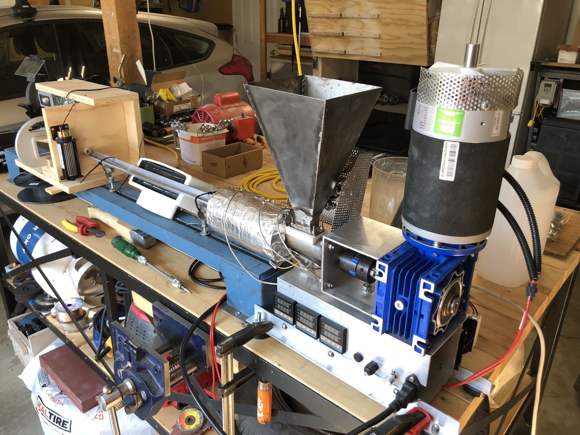
For the base frame, I cut a slot in the remaining 4x4" aluminium square tube for the PID controllers and mounted the geardbox/motor assembly to it using a little length of aluminium angle. As long as it is balanced (I will add feet later), it should be fine.
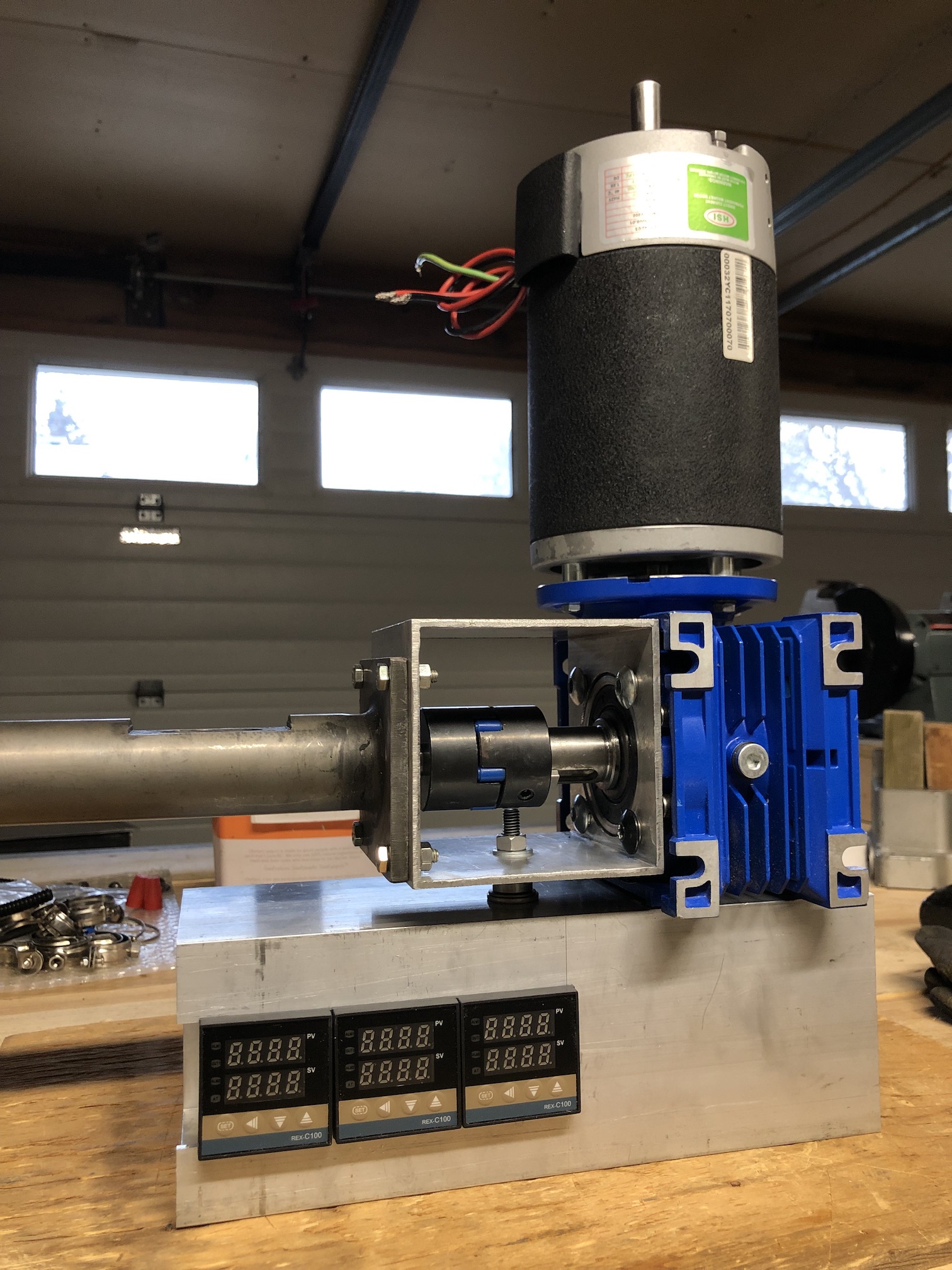
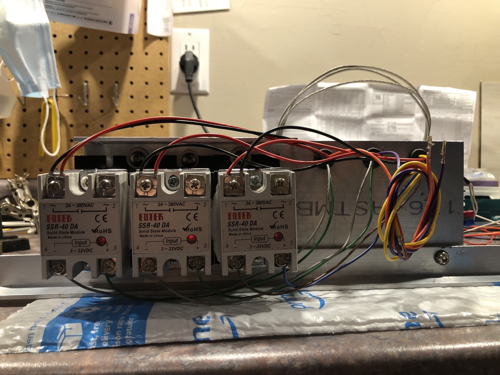
There are going to be three heating bands attached to the barrel and they will be controlled by REX-C100 digital PID controllers. These can be sourced more or less anywhere, including from AliExpress. I got mine shipped complete with a 40A SSR relay/heatsink and a thermocouple.
Wiring it all up is straight forward but tedious.
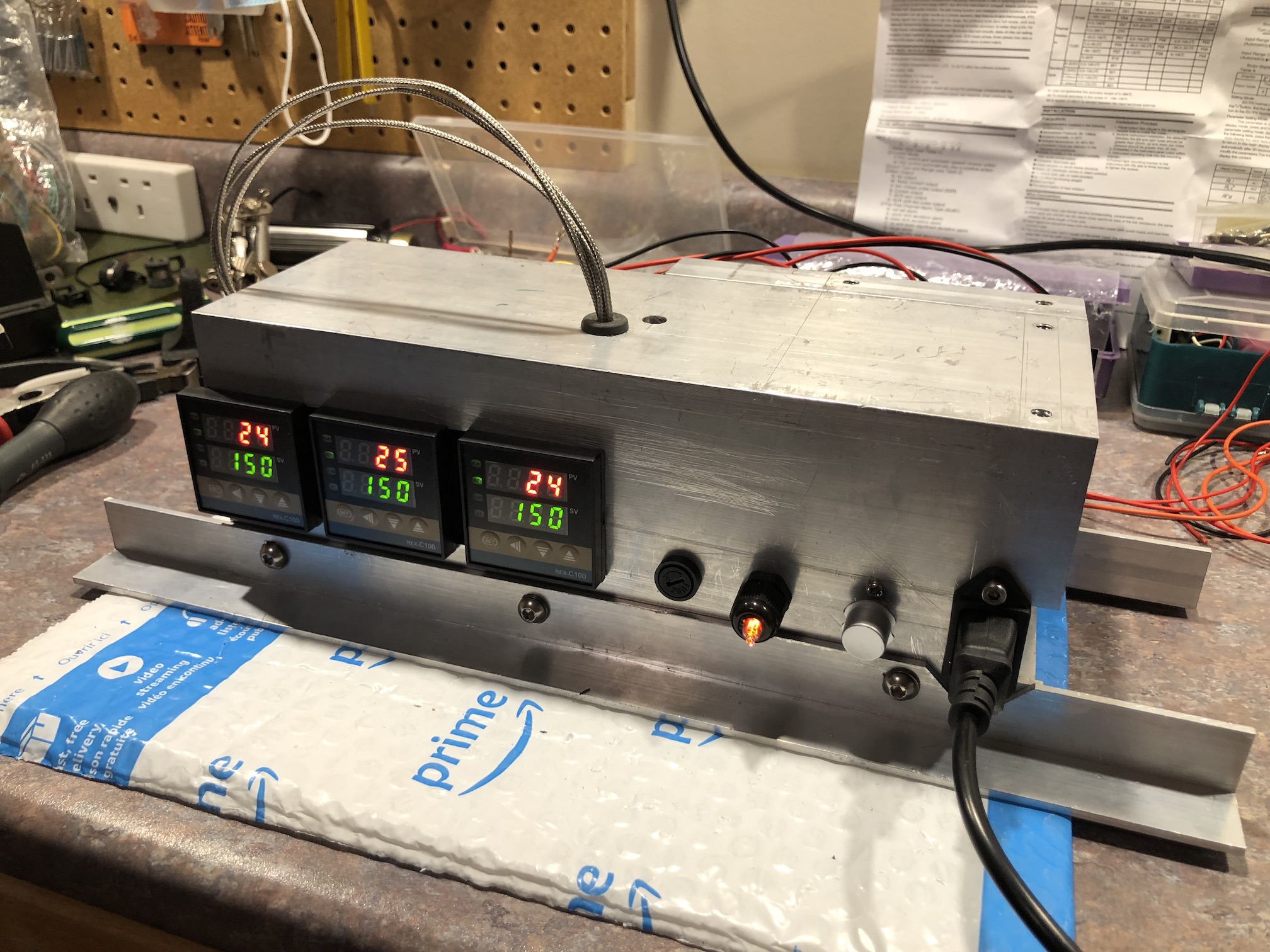
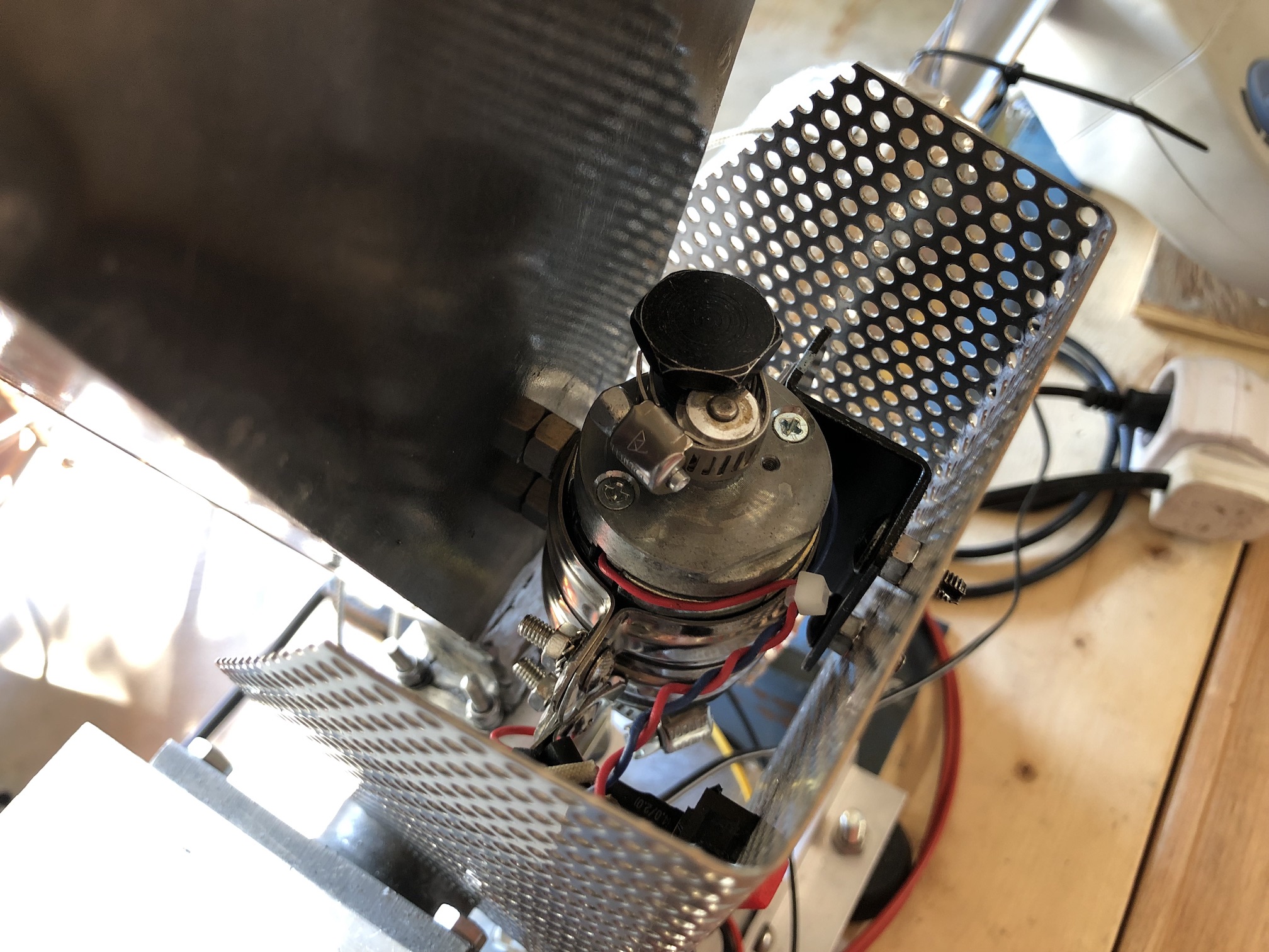
I added a 10A fuse, a neon indicator and a switch.
Eventually, this is what it ended up looking. Here's a video of an initial dry run.
I used pipe clamps with a welded M6 nut to keep the thermocouples in contact with the barrel, but I can see that the new barrels come with pre-drilled M6 holes already, making this part simpler.
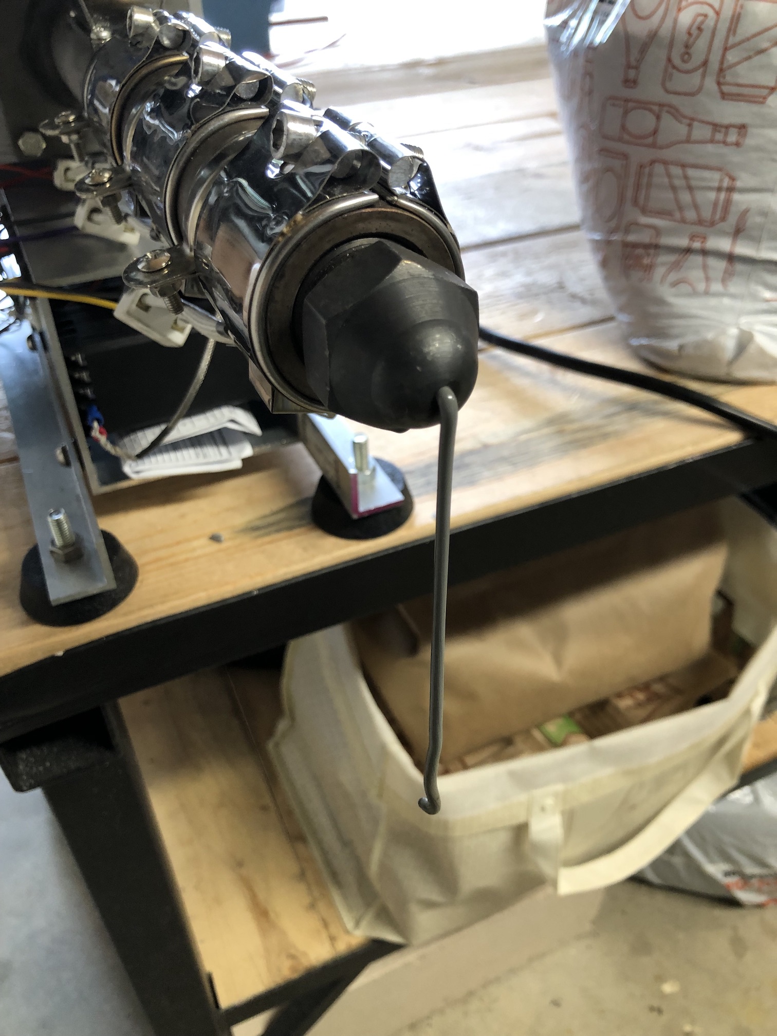
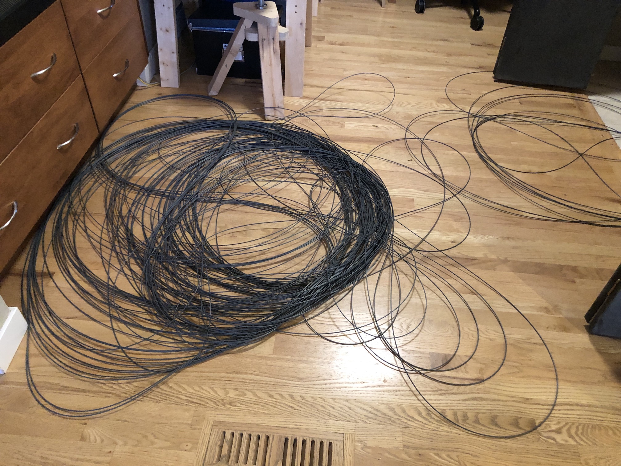
I rigged up the initial test run to see if the machine works generally and got some plastic noodles out of it.
Here's a photo I took of my initial rough product, not yet suitable for loading into the printer, because the thickness is not uniform (2.85mm or 1.75.mm depending on your printer nozzle). Luckily, this is a solved problem, but one which requires a couple of more pieces. The first of these is a gauge to measure the filament thickness.
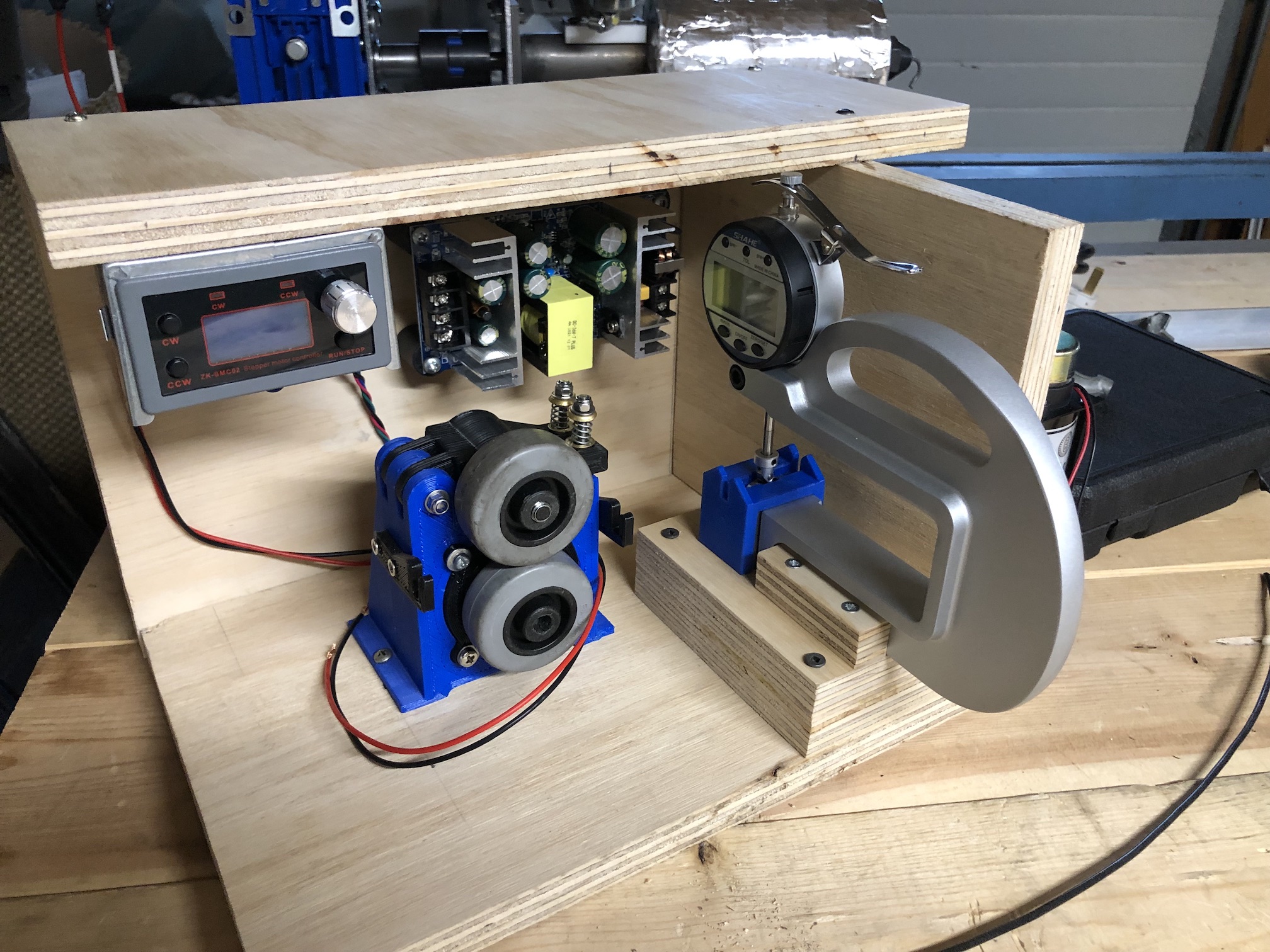
Filament thickness gauge
I prototyped a couple of different approaches and eventually settled for least manufacturing, higher cost solution, which involved a Shahe 0-10 mm digital thickness gauge with roller insert with 0.01 mm accuracy and a 3d printed guide by KillaCycle to feed it.
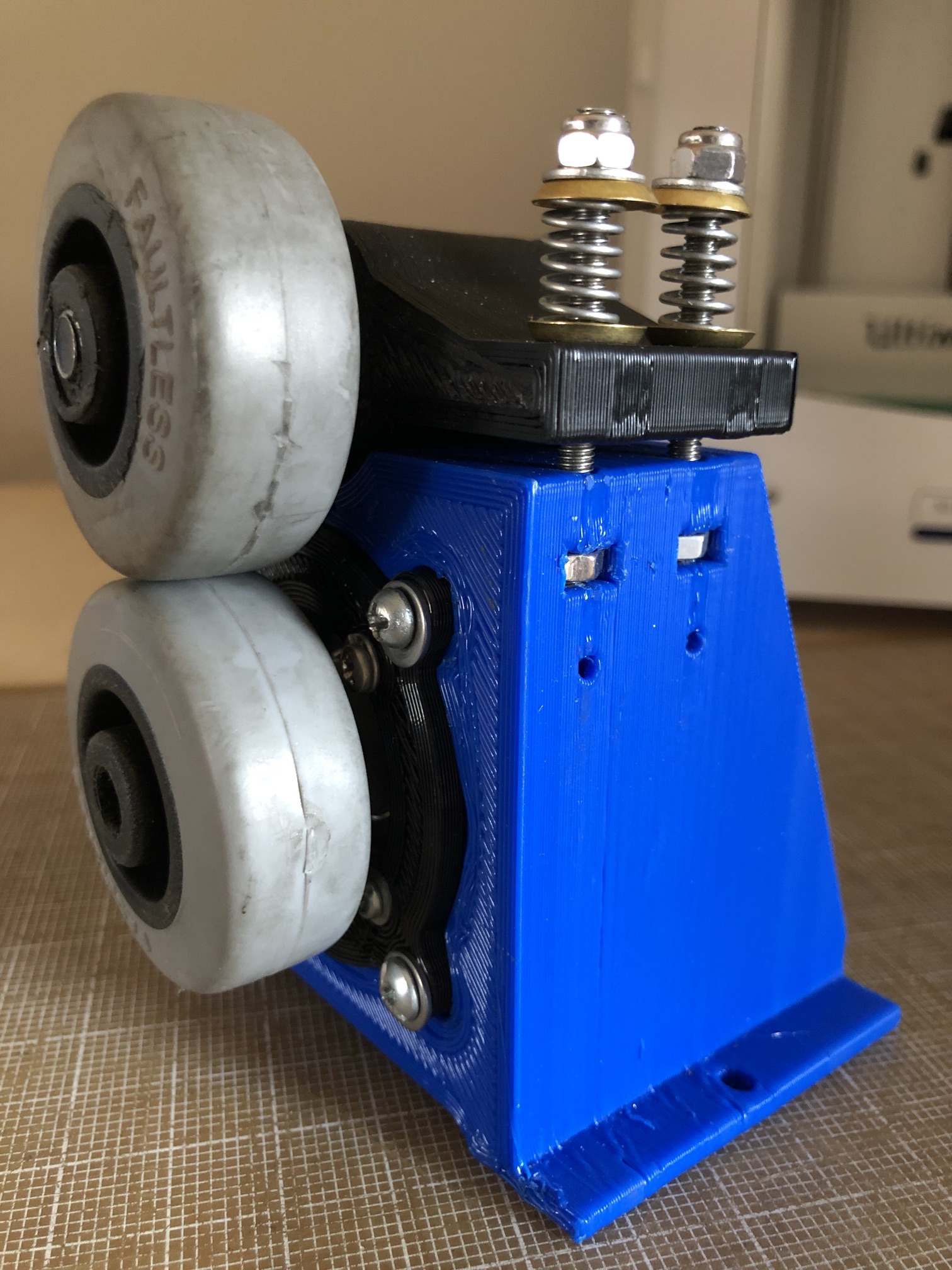
Filament puller
In order to control the final thickness of the filament, it has to be pulled at a higher constant rate, proportional to the extrusion rate. The nozzle produced a roughly 3mm plastic noodle, so the filament puller needs to pull it a little faster to thin it out, while the noodle is still hot. By the time the noodle gets to the filament puller, it has already passed through the thickness gauge, so that the pulling speed can be adjusted as required. The noodle must also be cool enough not to deform between the puller wheels, since the printer requires a round filament (i.e. a spaghetti, not a linguine).
For the puller, I used a Simple filament extruder puller
project by james_iii. To drive the puller, I purchased a NEMA17 Soyo stepper motor from Diigiit and a combined ZK-SMC02 controller/power-supply from AliExpress.
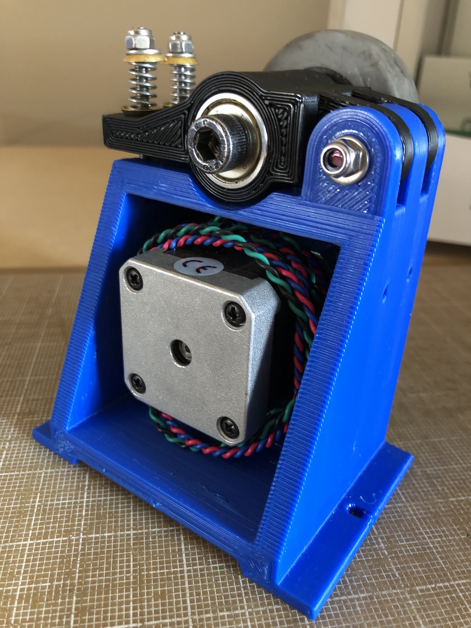
Rubber wheels came from Canadian Tire (sold as caster wheels), but these can be sourced from Amazon as well. I had to remove the metal pins to release the wheels and adapt them to the shaft. I had a spare shaft gear from my Ultimaker 2+ upgrade and I ended up gluing the wheel into that after boring out a slightly wider hole.
All the other bits, like power supplies, boost/buck DC converters can be sourced in the usual places. I made an enclosure from left over bits of sanded plywood.
Frame
I used an old basic wood lathe frame to line everything up and bolted it all down using various pieces of scrap for adapters.
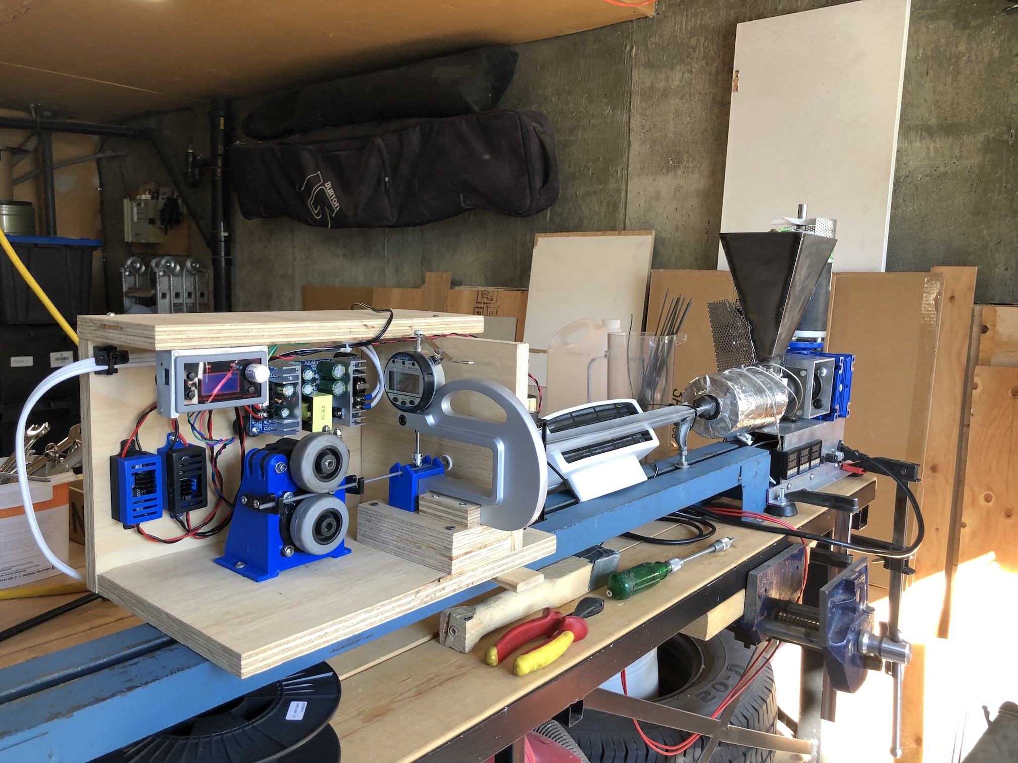
A length of aluminium angle between the hotend and the filament thickness gauge allows the filament to cool, with some help from a fan.
To keep the temperature of the extrusion as constant as possible, I've added a piece of fiberglass pipe insulation and wrapped it all up in aluminium HVAC tape.
Hopper
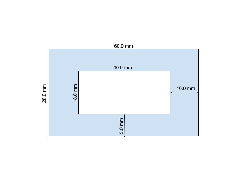
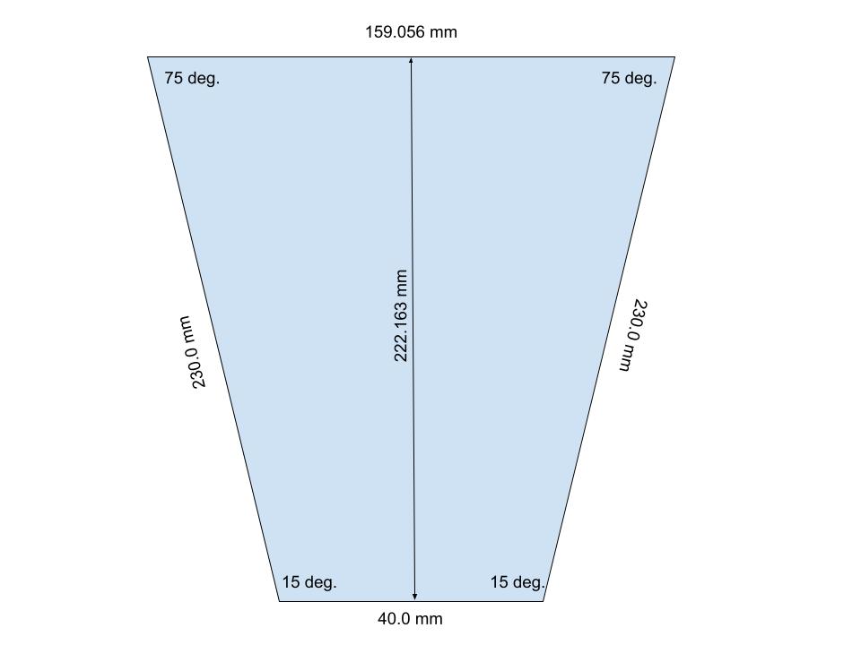
One thing I've not talked about so far is the hopper. This proved to be one of the most fiddly tasks in this project, because I didn't leave enough space for fastening the mounting plate to the barrel.
In either case, I sent the following design to a friend with a waterjet cutter and got back five 2-3mm pieces to weld together with a MIG welder (blowing big holes of course).

My barrel came pre-drilled with four M4 holes (not square!), so I had to transfer the hole locations using tracer paper onto the base plate. They didn't align very well still, so I had to hack the base plate to make it all fit. And in any case, because of the angle of the hopper and the very narrow space to work in, fastening the base plate to the barrel proved difficult. I used short lengths of M4 threaded rod and nuts to hold it in place. I also added a PTFE spacer between the barrel and the hopper base to prevent the bottom end of hopper from heating up and melting the plastic prematurely. Not doing this may result in shredded plastic feed gumming up and clumping together, blocking the plastic from being fed into the screw.
My next hopper would sit on a piece of square pipe (neck), which would allow easier fastening to the barrel. I would probably also consider making a wider baseplate and fastening it to the barrel using a clamp of some sort from underneath. The straight neck would allow for easier mounting of a propeller/agitator to keep to material disturbed/flowing.
The other improvement I made to keep the plastic fed at uniform rate is a vibrator. I had a spare DC motor laying around, so I attached heavy bolts to each end eccentrically using hose clamps and made a cage in order not to get a bolt in the eye. It works reasonably well, but I still found I needed to manually agitate with a long screw driver occasionally and/or not to feed to quickly and overload the hopper.
Production notes
here's a short video of the unit running with ABS plastic
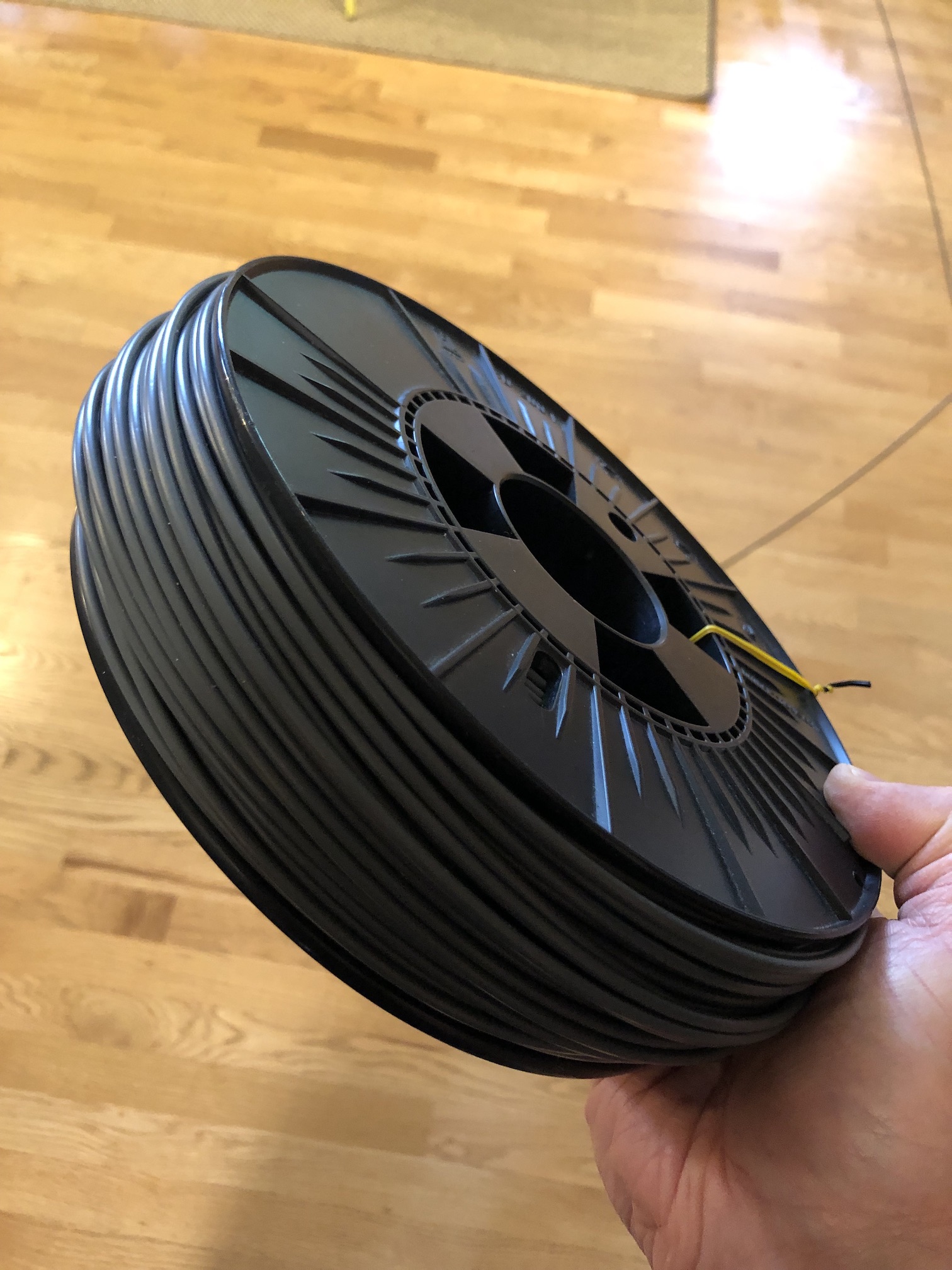
I haven't built a spooler as yet to collect the filament, so the process of transferring noodle bird nests onto reels is currently manual.
The most important variables I found during the process in order of importance
- Feeding speed, screw rotation speed and hopper agitation
- Barrel temperature
- Filtering
- Cooling
- Filament puller speed
Overfilling the hopper will almost certainly cause a dead space above the screw and I often got under-extrusion as a result. Fine pelletised feed may help here, but the pieces coming out of my Shredditor are big enough to require constant feed management. When I had the screw rotating too slow, I noticed the material was sitting around the hot feed end longer, starting to clump up and blocking the feed entrance. Vibration induced agitation helps a bit, but it's still not 100% effective. I could perhaps try a spinning propeller mounted perpendicularly above the screw constantly moving material around to replace or supplement the vibration mechanism.
For ABS plastic, which came from the various treadmill panels, I've settled on the following barrel temperatures (right hopper to left nozzle) 150C/155C/165C. These seem to be working well, and I am not getting any gumming/clumping at the feeding end.
There definitely needs to be some sort of filtering as there is a lot of crap that comes with the plastic, including metal shavings from the extruder knife box. For injection moulding, no filtering is probably fine, but not for 3d printer filament production. I stuck some old hard disk magnets on the hopper neck to catch the metal shavings, so that part was easy. For the nozzle filter, my first attempt involved a toonie, since the coin was exactly the right diameter for the inside of the barrel. I drilled 1.5mm holes as per PP design and screwed it together by tightening the nozzle. During my initial runs, I was constantly getting blockages in my 3d printer nozzle, even using the largest 0.8mm size. I took the nozzle off to inspect my filter and found that the coin deformed and the brass insert popped out. So filter v2 was made from two pieces of steel mesh sizes 20 and 30, spaced by suitably sized washer/spaces and held together in place by the tightening of the nozzle barrel against the spacers. This filter system seems to be working well so far.
If the noodle gets to the filament puller still too hot, it will be formed into a linguine and not a spaghetti. So it's important to air cool the filament enough before it gets into the puller.
The least important of the variables is the filament pulling speed. I found that as long as the filament is +/- 0.2-0.3mm of the target thickness, the printer doesn't care that much and the prints come out adequate. I have bigger problems with keeping the plastic from warping to be honest.
Conclusion
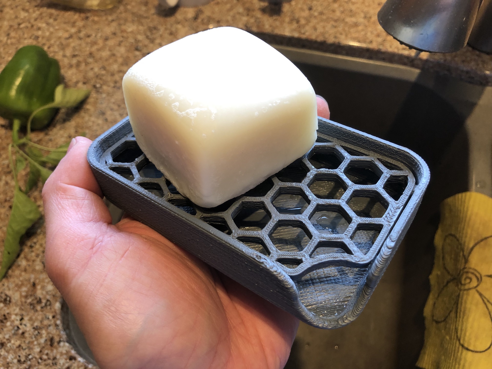
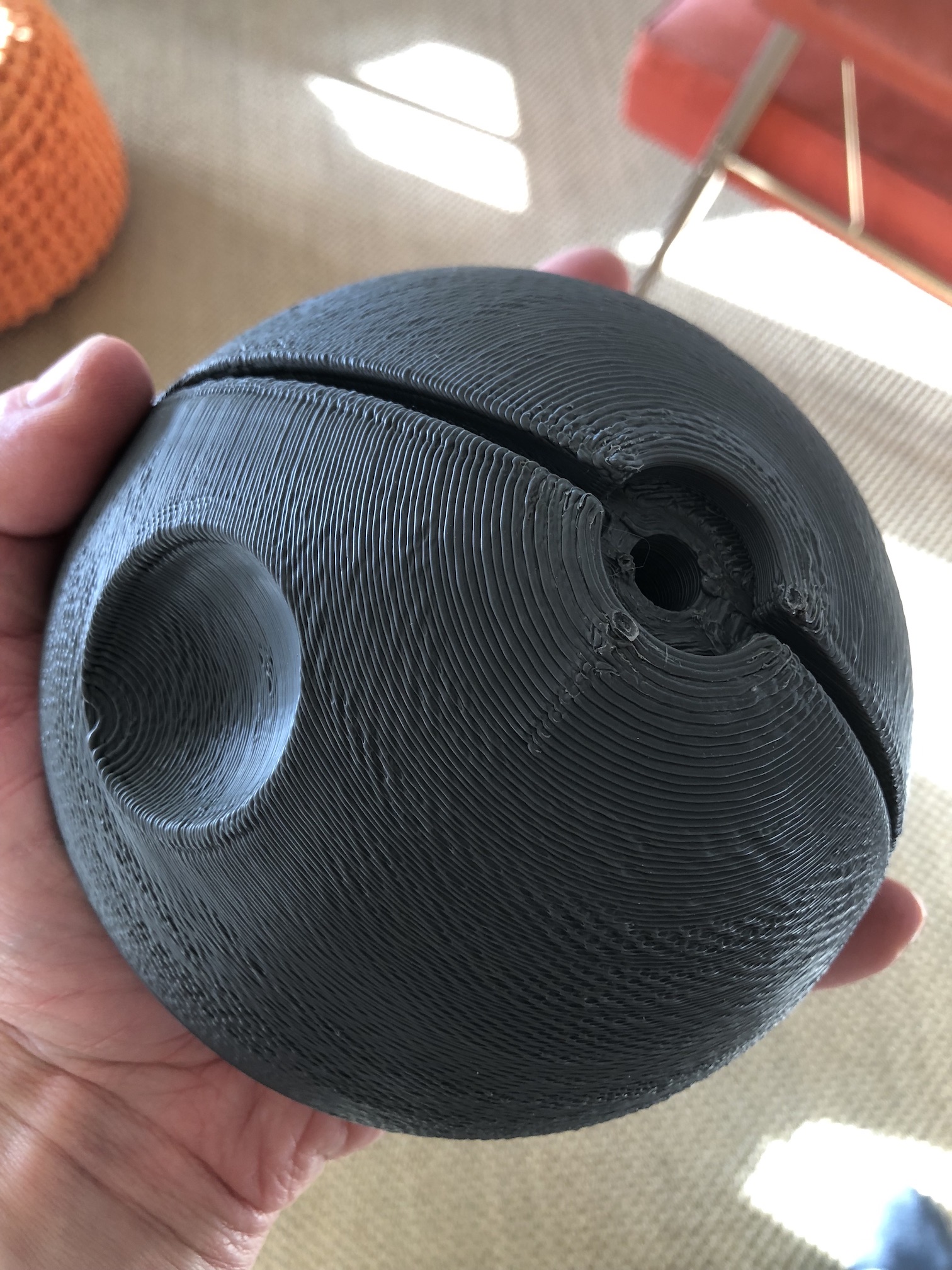
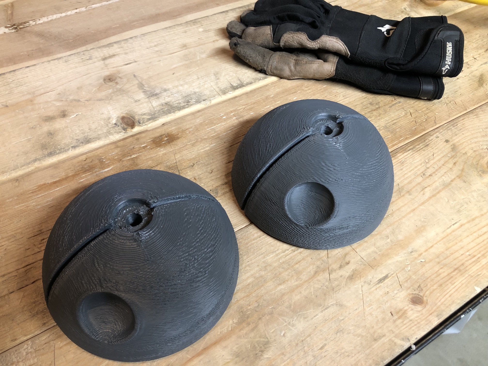
So far, I've reprocessed about half of the donor treadmill ABS plastic and printed a few things, like a soap dish and death star climbing holds.
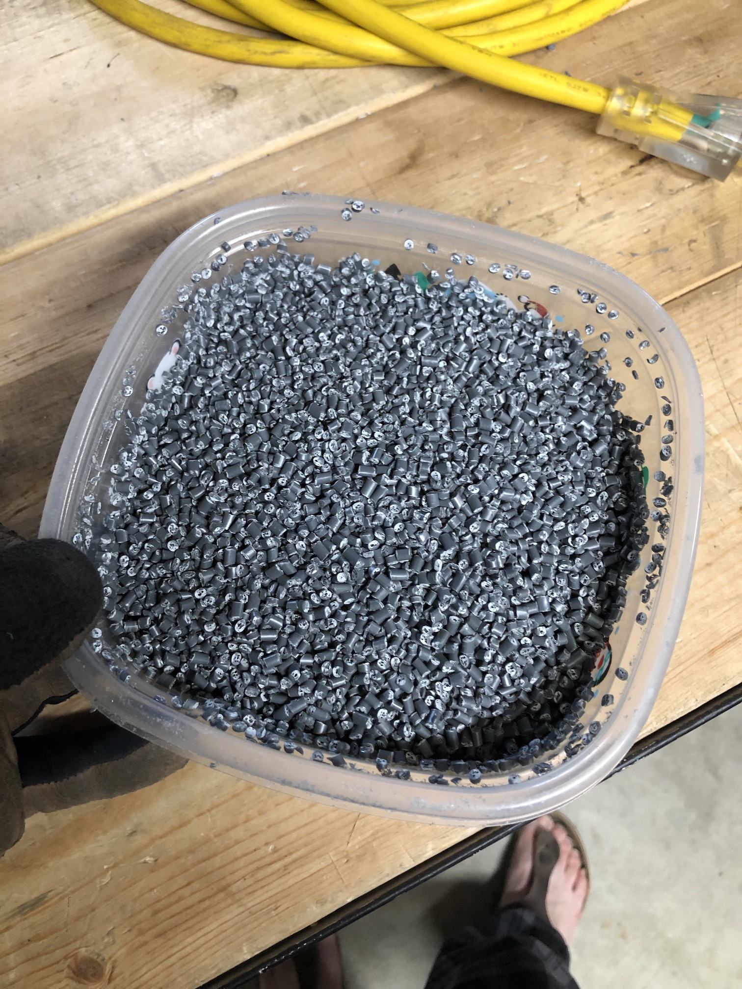
A note on waste... During prototyping runs, I produced a lot of unusable filament. It helps to have a pelletising facility. Filament doesn't shred very well due to its geometry - a lot of long pieces simply fall through the shredder.
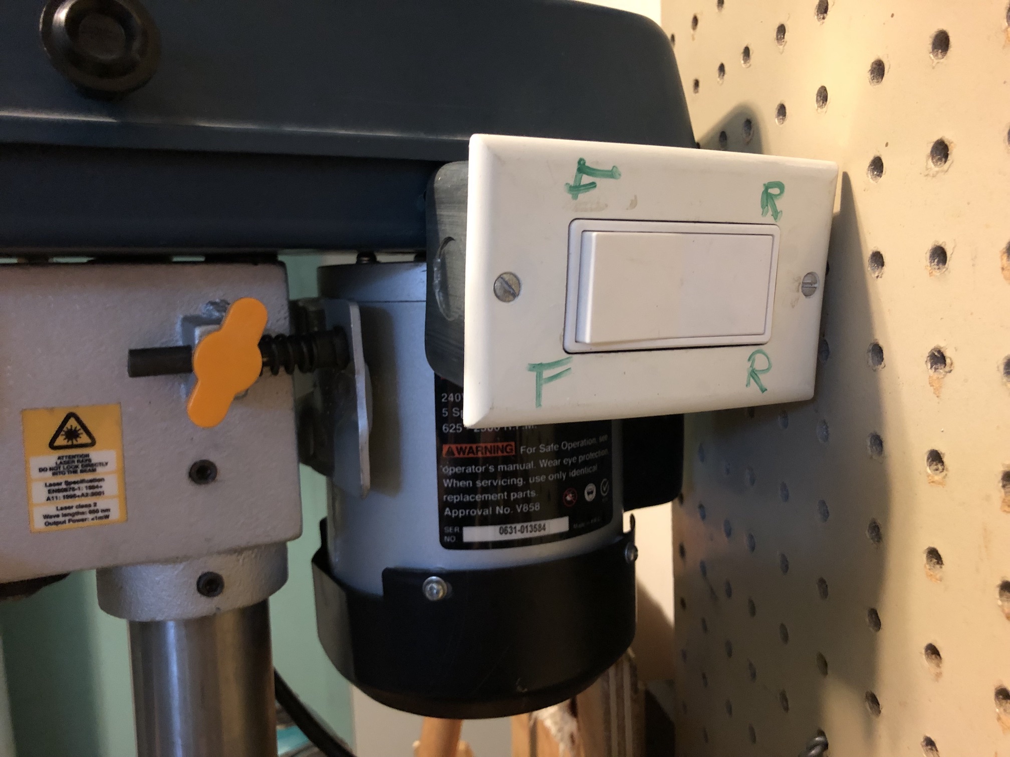
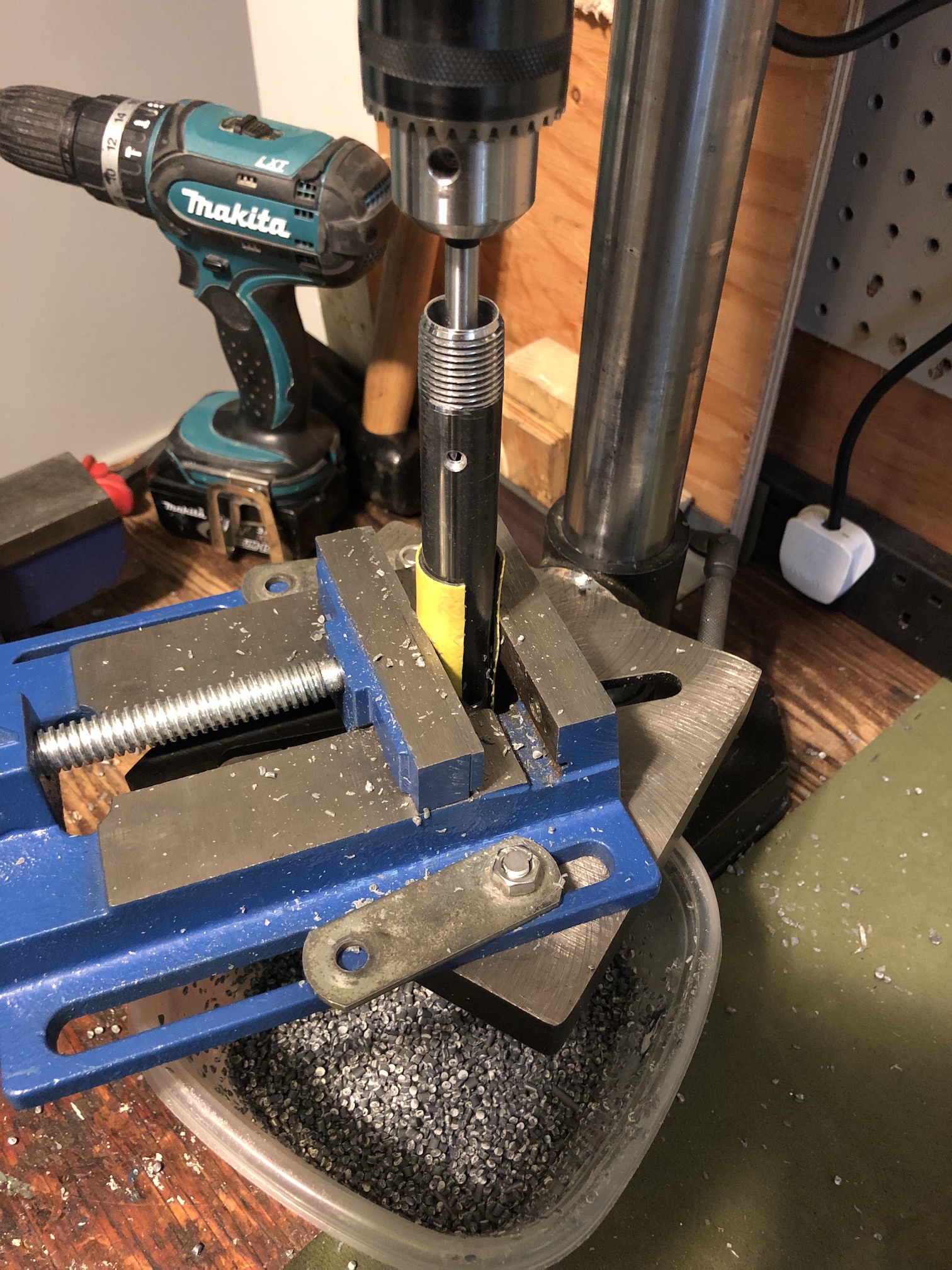
Inspired by Thomas Sturm's design, I made a drill press pelletiser using a 5/8" Forstner bit and a 1/2" black pipe. In order for the pelletiser to work, the drill press needs to be spinning in reverse, otherwise the material will come out of the top of the pipe, making a mess.
I ended up pulling my drill press motor apart and wiring a DPST light switch to reverse it.
Next steps...
Some obvious next steps would involve taking manual labour out of the process as much as possible. All of the motor controllers as well as the roller thickness gauge have serial output, so I am planning to read their outputs with some old/cheap SBC (e.g. RaspberryPi 1) and write some software to automatically adjust screw rotation speed and pulling speed based on the resulting thickness of the filament.
The other obvious improvement would be to automate the feeding and the spooling of the resulting filament, the first one being more important in my opinion than the second.
🫠👍
